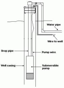
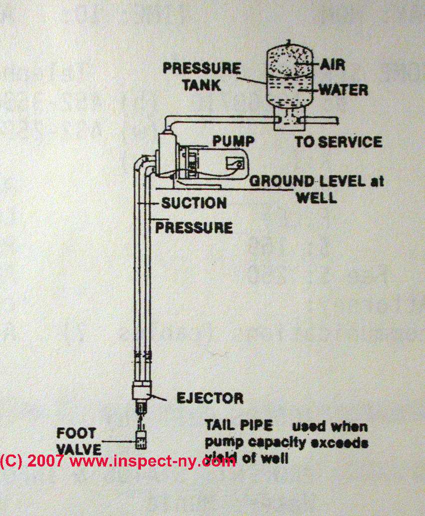
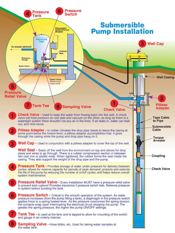
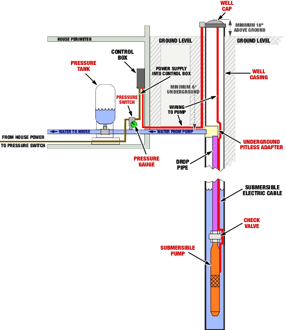
40 well pump system diagram
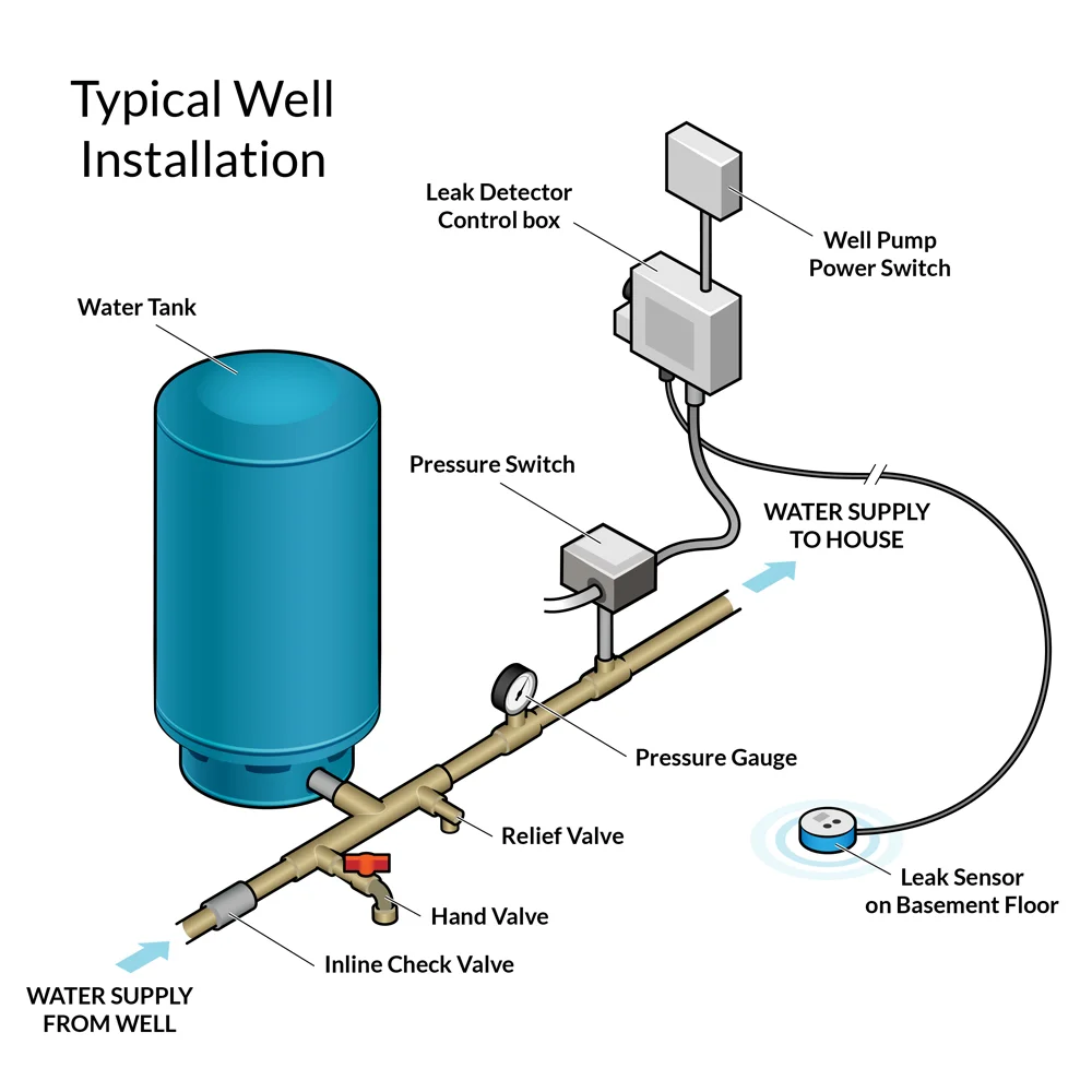
SHALLOW WELL JET PUMPS CONT. two unions between the pump and the well. If vertical pump is being used, adapt the 1 1/4" and 1" pipes directly into the 1 1/4 " and 1" taps in th e pump housing and adapt some type of supports or legs from the foundation to brackets on the pump housing to support the weight of the pipes, ejector or jet in the Water Pressure Tank Installation Diagram. The image below shows the typical installation diagram of a well pressure tank, as well as other components of a well system. Image: Lakeland Water Pump How a Bladder Pressure Tank Works. A bladder pressure tank is a steel tank with a bladder inside which looks like a balloon.
An overview and description of typical residential well water system components. Pressure switch, well tank and other components explained.

Well pump system diagram
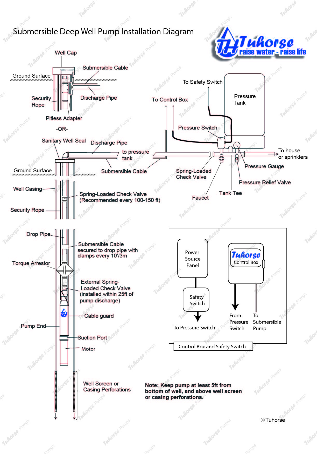
Replacing your submersible water pump can be easy, but before pulling that pump from the ground you need to safely assess what type of system already ... Deep Well Pump Installation Diagram Well Water System, Water Well, Water Systems, Shallow. G. Gaberial. 81 followers. More information. Well Water System. March 21, 2019 - Well pump systems have multiple components that work together to bring water to your insured’s home or business. This labeled diagram will help make handling this type of claim a little easier. Well pump claims can be difficult and expensive to settle. Make sure you’re prepared to handle ...
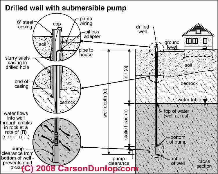
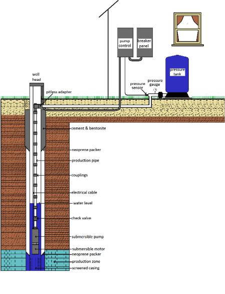
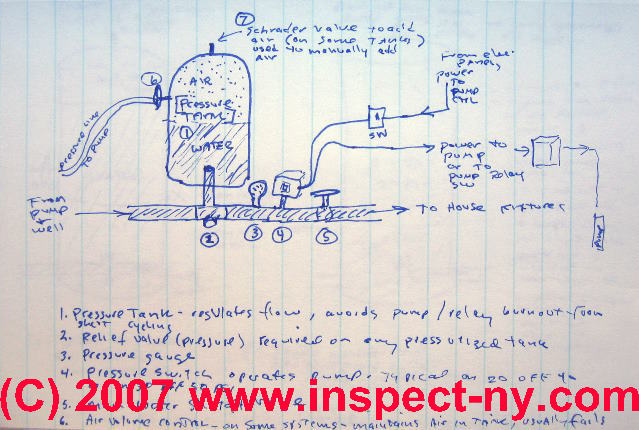
Well pump system diagram. What types of wells use a two-line jet pump for water delivery. From what depth can a two line jet pump deliver water? Types of wells and water supply systems and what to watch out for with each. Well pump & water tank diagnosis & repair procedures. Electric pump motor troubleshooting guide ... August 12, 2021 - Need to install a submersible pump? Click to watch the most complete set of submersible pump installation instruction on the internet. Home > Technical Information > Pumps Technical Data > Submersible Well Pump Technical Data > Submersible Well Pump Accessories Installation Diagram . Submersible Well Pump Accessories Installation Diagram . This illustration is for educational purposes ; It is not intended as an installation guide. The page top sketch is expanded by detailed photographs as we explain each of the components and controls of wells, pumps, and water tanks. In our sketch (sorry the author is a technician but not an artist), you can identify the basic components of a private well system (listed next) but as ...
For example, if the well uses a pressure tank, a water treatment system must be installed after the pressure tank to avoid causing damage to the well pump. When you open a faucet in your home or turn on the shower or bath you expect water to flow at a certain flow rate and with good water pressure. Before Installation. Well pump installation can be dangerous when dealing with water and electricity, so extreme caution must be taken. Before getting started, look up your owner's manual and read over the precautions and all other warnings before beginning the installation. The manual will contain important safety precautions, wiring diagrams, tools required for assembly, proper grounding ... Diagrams --Typical Pump Installations. The information provided here is for educational purposes only. Technically qualified personnel should install pumps and motors. We recommend that a licensed contractor install all new systems and replace existing pumps and motors. Failure to install in compliance with local and national codes and ... Well Diagram. The quality water system products described here and illustrated on the front page are some of the Baker Water Systems products used in a typical well system. (The section in the catalog where these items can be found is located in parentheses) This list and the illustration on the front page are not intended as an installation guide.
PUMP 3 1. Check Valve Located at the top of the pump to prevent back flow into pump and hold the head of water in the system. 2. Torque Arrestor Installed directly above Submersible Pump to protect pump and well components from starting torque damage. 3. Safety Rope A safety line from the top of the well to the pump. 4. Pitless Adapter September 11, 2021 - An introduction to well pump systems which explains the mechanics behind jet and submersible pumps as well as basic knowledge, maintenance, and troubleshooting information. Once the pump is immersed, reconnect everything and make sure the system is working properly. If the pump bottoms out before it's submerged, this often means a new well has to be drilled. Here's a tip for your customers: The water depth in a well does fluctuate, and they can chart this by doing a simple test. The Well Pump. The well pump, or water pump, is the heart of the system. It is what pumps water upward and into the household or designated water system. The two most popular types of pumps used today are jet pumps and submersible pumps. Both pumps rely on centrifugal force in order to force water upward. Spinning rotors, known as impellers ...
Pitless adapters provide wells with a sanitary — and frost-proof — seal between the well casing and the water line running to the well system owner's house. After a frost line is determined for the area where the well is being installed, the adapter is connected to the well casing below the frost line.
June 24, 2016 - Skillings and Sons provides well drilling services for drinking, geothermal and agricultural use. Skillings and Sons also provides quality maintenance and repair service.
November 14, 2017 - Jet pumps are mounted above the well, either in the home or in a well house, and draw the water up from the well through suction (see Single-Drop Jet-Pump System diagram on next page). Because suction is involved, atmospheric pressure is what's really doing the work.
Oct 8, 2015 - Submersible Well Pump Accessories Installation Diagram.
(21) Pump Saver Adjustable, solid state control monitors system load conditions to protect pump motor from dry well, flow loss, rapid cycling, slow recovery, air lock and locked rotor problems. (22) Lightning Arrestor Protects pump motor and controls from voltage surges caused by lightning, switching loads and powerline interference. (23) Ball ...
100. Bubbler System Control Diagram (With Electric Pressure Switches) Wet/Dry Well ....PS-E2-1B 101. Float System Control Diagram (Wet/Dry Well) .....PS-E2-2 102. Pump One Control Diagram (Wet/Dry Well) .....PS-E2-3A 103.
June 18, 2017 - Have a question about well water, spring water, rainwater treatment? I answer your questions about water quality problems and well water treatment.
System pressure: It is important to take the total system hydraulics into the calculation and not only the pump's well setting when selecting valve type and model. In general Flomatic valves are pressure rated 400 psi or 920 feet of water pressure. This does not mean that a valve can be set at a well depth of 920 feet.
Oct 20, 2016 - Architecture, design, and stories to inspire the space around you.
Water Well. Water Systems. Well Water Pressure Tank. Well Pump Repair. Submersible Well Pump. Well Tank. Plumbing Drains. Troubleshooting A Water Pressure Bladder Tank. Quick check for blown bladder 1 Turn off pump 2 Open faucet wait for flow to stop leave open 3 Shake bladder tank 4 If it still has water in it it is.
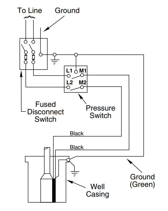
Two Wire Submersible Well Pump Diagram | Wiring Library - 2 Wire Submersible Well Pump Wiring Diagram. Wiring Diagram arrives with several easy to adhere to Wiring Diagram Instructions. It really is supposed to aid each of the typical consumer in developing a proper system. These guidelines will likely be easy to understand and implement.
Well Diagram. The quality water system products described here and illustrated are some of the Baker Water Systems products used in a typical well system. This list and the illustration are not intended as an installation guide. Check local codes for actual requirements and restrictions. (Scroll over Numbered part for Detailed View)
Sep 19, 2012 - A leading Manufacturer of quality products for residential and light commercial water systems, sewage, effluent, sump pump, water filtration, and treatment systems. Lead-free and stainless products for every application.
The New Jersey Ground Water Association (NJGWA) is composed of well drilling contractors, pump installers, suppliers, manufacturers, engineers, scientists and other ground water professionals who strive to provide the best services in the New Jersey water well industry.
pump. This will center the pump in the well and keep the pipe from twisting due to torque created by the pump motor. 13. IMPORTANT! Wire splices should be staggered, securely crimped and weatherproof. Heat shrink splice kits have a sealant that makes the joint completely waterproof. 14. Pump should be suspended some distance off the bottom
If you're replacing your deep well pump, our expert from Everbilt will guide you. This tutorial for an Everbilt jet well pump installation shows you step by ...
Jet pumps usually come with a 30-50 pressure switch factory installed on the pump. If replacing the switch we recommend using one with a 30-5 psi setting. 1. Deep well jet systems are used when the water depth is between 20' and 80'. For wells deeper than 80' a submersible pump system is recommended. 2. We recommend a captive air pump tank.
Anatomy of a Well: Pump. One of the most important water well components, the pump, acts like a heart pumping water throughout the system. Electric pumps draw water from inside the casing and deliver it through high-density polyethylene black plastic water pipes into a home. This special piping is highly durable and affordable to repair and ...
How to install and wire a well pump installation guide water wiring troubleshooting repair diagrams submersible 6 lessons for doing it right everbilt 3 4 hp 2 motor 10 gpm deep potable efsub7 122hd the doityourself com community forums 123hd lovetoknow three typical 120v directly into pressure switch terry love plumbing advice remodel diy professional forum rs485 hydrostatic… Read More »
Well Diagram. This illustration is intended to represent some of the components that can be included in a water well system and is not intended as an installation guide. Check local or state codes for actual requirements and restrictions.
The system in Figure 2 is a typical domestic water supply system that takes it's water from a shallow well (25 feet down max.) using an end suction centrifugal pump. Figure 2 For more details on the construction of jet pumps see this article: specialty pumps .
March 21, 2019 - Well pump systems have multiple components that work together to bring water to your insured’s home or business. This labeled diagram will help make handling this type of claim a little easier. Well pump claims can be difficult and expensive to settle. Make sure you’re prepared to handle ...
Deep Well Pump Installation Diagram Well Water System, Water Well, Water Systems, Shallow. G. Gaberial. 81 followers. More information. Well Water System.
Replacing your submersible water pump can be easy, but before pulling that pump from the ground you need to safely assess what type of system already ...













0 Response to "40 well pump system diagram"
Post a Comment