37 diverging mirror ray diagram
Ray 1 is parallel to the axis and refracts as if from F. Ray 2 heads towards F' before refracting parallel to the axis. Ray 3 passes straight through the center of the lens. image is always virtual, upright and reduced O F I F' Ray diagram for diverging lens Description of how to draw ray diagrams for diverging lenses for grade 10 science.
Ray diagrams for diverging (concave) lens. If an object is on one side of the concave lens, the concave lens can form the image of the object. If the position of the object on one side of the concave lens is known, how to draw the image formation of the object? Suppose an object is on the left side of the concave lens as shown in the figure below.
Diverging mirror ray diagram
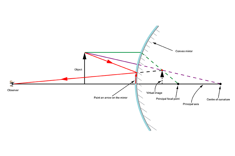
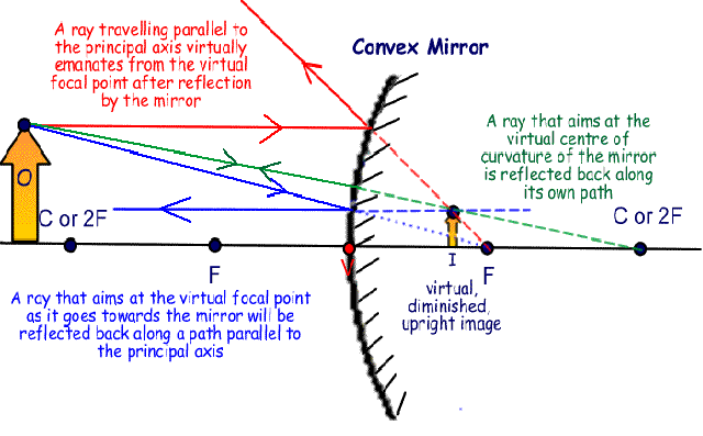
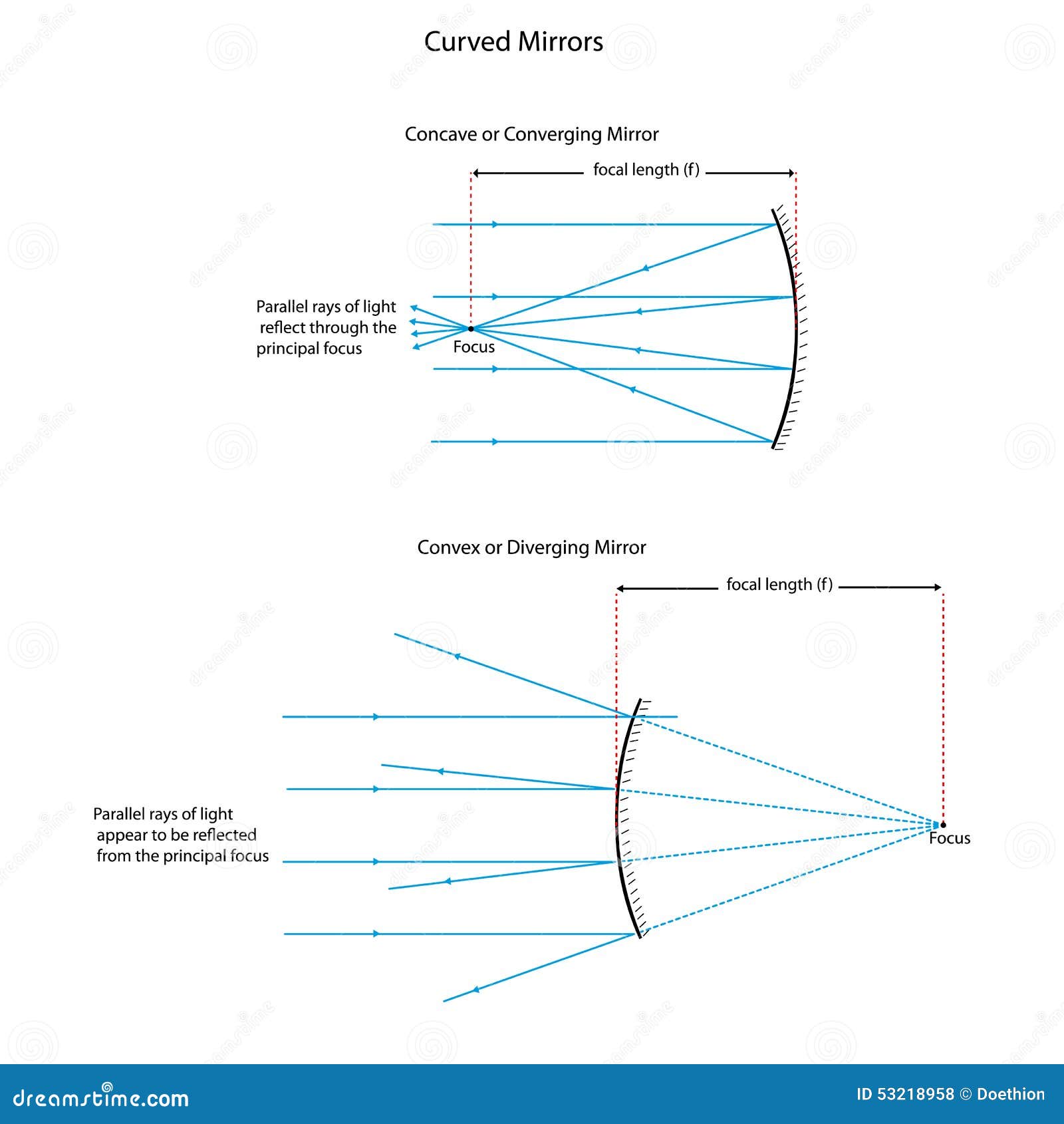
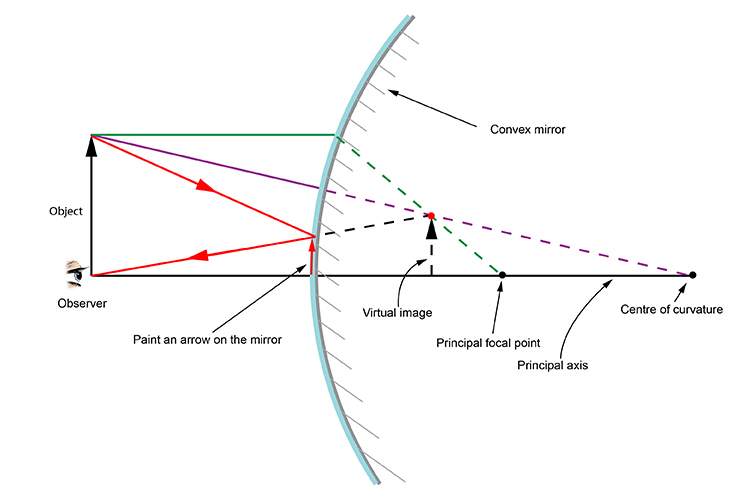
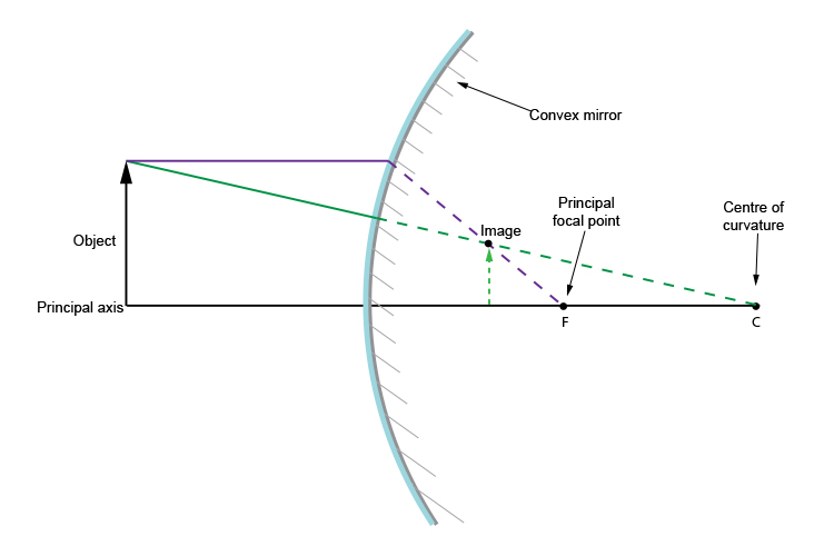
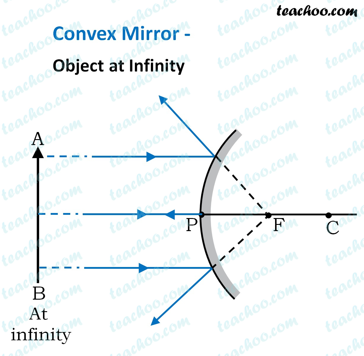
•A convex mirror is sometimes called a diverging mirror. •The rays from any point on the object diverge after reflection as though they were coming from some ... Ray Diagram for a Concave Mirror, p < f •The object is between the mirror and the focal point. •The image is virtual. •The image is upright. Plane mirror- Definition, Properties and Ray Diagram. Mirrors are defined as one side-polished surface that can reflect the light rays. Plane mirrors in physics are the ones that have a flat reflecting surface and produce always a virtual image. In this tutorial, we review the most important topics in the plane (flat) mirrors in physics ... Diverging mirrors, sometimes refered to as "shoplifting mirrors," only form reduced, virtual images.As can be seen in this diagram below, the incident rays (yellow) all begin on the top of the object (red arrow) and are each scattered from the mirror's front, convex surface.The reflections when dotted back (green lines) form a virtual image (gray arrow) behind the mirror.
Diverging mirror ray diagram. Ray diagram practice sheet. Our conceptual classes need to be able to handle ray diagrams for converging and diverging mirrors and lenses. That's really only six different diagrams: Converging lens with an object inside the focal point. Converging lens with an object outside the focal point. Diverging lens*. Convex Mirror Image. A convex mirror forms a virtual image.The cartesian sign convention is used here.. Using a ray parallel to the principal axis and one incident upon the center of the mirror, the position of the image can be constructed by back-projecting the rays which reflect from the mirror. 12 draw a ray diagram for an object placed 60 cm from the surface of a converging lens with a focal length. 36 ray diagrams for convex diverging mirrorsdoc. 18 biology projects due. The concave mirror shown below has an object placed 20cm in front of it. The image location for either mirrors or lenses can be found by a ray diagram. A ray diagram is constructed using the following rules for a converging (or diverging) lens: Parallel incoming rays will be refracted towards (convex lens) or away from (concave lens) the focal point.
Attachments. ray diagrams amherst ray diagrams • three rays leave one point on an "object" 1 point f of a diverging lens the image is 1 virtual upright and diminished. Diagram 2 Light ray diagrams which show how the image in concave mirror changes depending on the object distance. READ Blood Flow Through the Body Diagram. Plane Mirrors. Drawing a ray diagram is fairly simple for a plane mirror. Firstly we should draw an incoming ray: Figure 1: A diagram showing a ray incident on a plane mirror from an object. Notice that the object is clearly labelled and the direction of travel is indicated with an arrow on the ray. This Demonstration lets you visualize the ray diagrams for converging and diverging lenses. By manipulating the object and lens locations, you can create real or virtual images. The rays parallel to the principal axis and the ray through the center of the lens are drawn.Locators allow you to drag both the object and the lens. You can change the focal length using a slider. Ray diagrams concave mirrors the method for drawing ray diagrams for concave mirror is described an observer can sight from which all the reflected rays appear to be diverging Diagram 1 Diagram 2 drawing converging concave mirror ray diagrams how to draw ray diagrams for a coverging concave mirror.
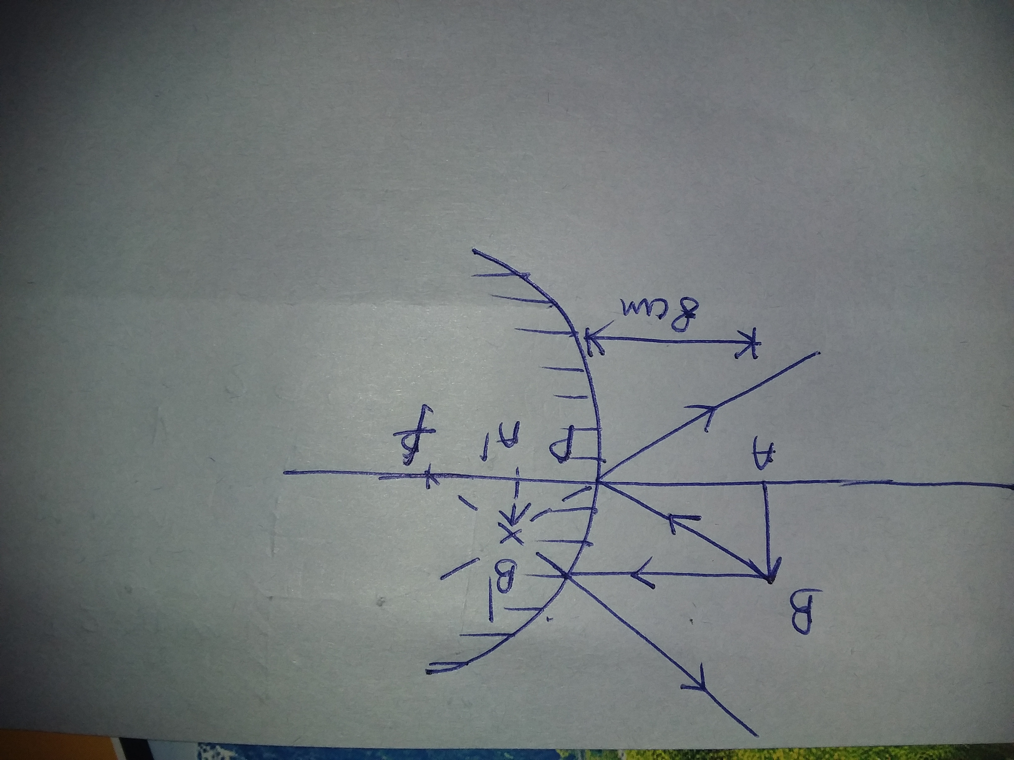
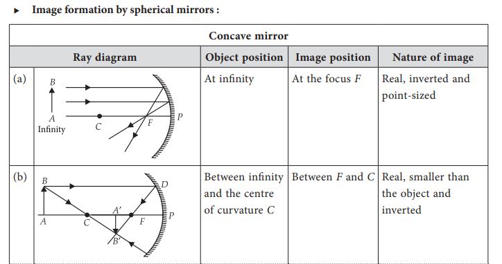
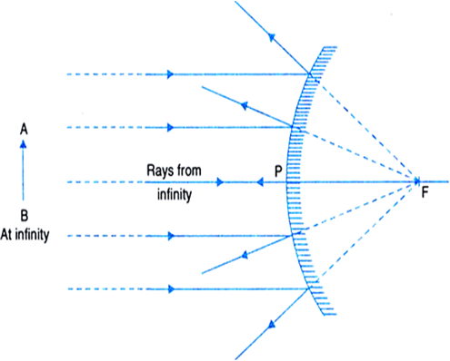
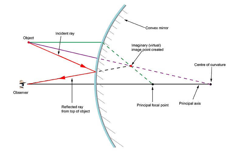
Case 1 - Object is Placed at infinity. In this Case, Object AB is kept far away from mirror (almost at infinite distance) So, we draw rays parallel to principal axis. Since ray parallel to principal axis passes through the Focus. Both rays meet at focus after reflection. Hence, Image is formed at Focus. And it is very very small. We can say that. A ray diagram shows the path of light from an object to mirror to an eye. A ray diagram for a convex mirror shows that the image will be located at a position behind the convex mirror. Furthermore, the image will be upright, reduced in size (smaller than the object), and virtual. This is the type of information that we wish to obtain from a ray diagram. In this lab, you will construct the THREE ray diagrams for diverging mirrors. In each diagram, use an arrow, 1.0 cm tall, pointing upwards as the object. Label it with an O. For your convenience, blank diagrams will objects already provided are located on this page -- in IE use landscape mode with margins of 0.5. Ray Diagrams for Lenses. The image formed by a single lens can be located and sized with three principal rays. Examples are given for converging and diverging lenses and for the cases where the object is inside and outside the principal focal length.
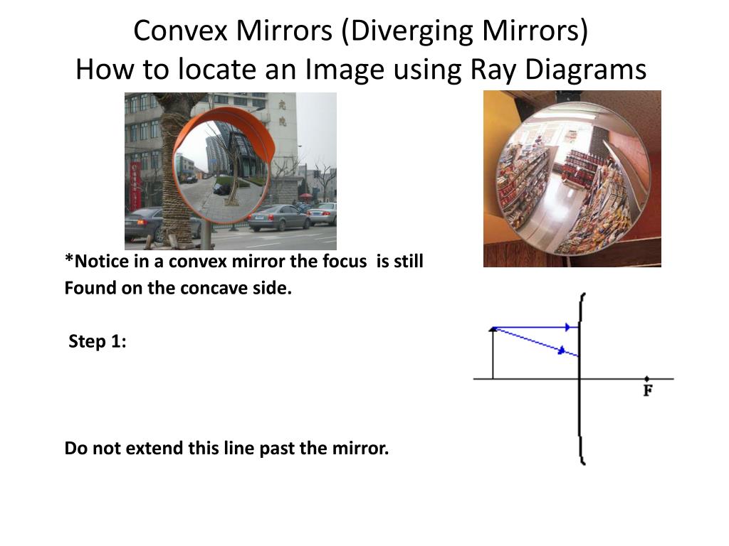
The diagram on the left shows an object (red arrow) in front of a diverging mirror. The ray (solid blue line) is the one that would have passed through the focus of the mirror and is reflected parallel to the axis. The shaded blue arrow represents the image. (The other two rays used to locate the image are not shown for clarity.) Notice that ...
5. Using the Data Sheet marked \Mirror Ray Diagram # 1" and the rulers provided, draw a ray diagram to locate the image of an object 14 cm from the mirror. Use the height determined above as the height of the object on your ray diagram. Each person in your lab group should draw this ray diagram. v:F06
How to draw a ray diagram for a diverging (convex) mirror. Please visit www.studyphysics.ca
Here you have the ray diagrams used to find the image position for a diverging lens. A diverging lens always form an upright virtual image. Ray diagrams are constructed by taking the path of two distinct rays from a single point on the object: A ray passing through the center of the lens will be undeflected. A ray proceeding parallel to the principal axis will diverge as if he came from the ...
In this lab, you will construct the THREE ray diagrams for diverging mirrors. In each diagram, use an arrow, 1.0 cm tall, pointing upwards as the object. Label it with an O. For your convenience, blank diagrams will objects already provided are located on this page-- in IE use landscape mode with margins of 0.5.
The ray diagram constructed earlier for a diverging lens revealed that the image of the object was virtual, upright, reduced in size and located on the same side. Any incident ray traveling parallel to the principal axis of a diverging lens will refract through the lens and travel in line with the focal point (i.e., in a direction such.
A ray diagram shows the path of light from an object to mirror to an eye. Incident rays - at least two - are drawn along with their corresponding reflected rays. Each ray intersects at the image location and then diverges to the eye of an observer. Every observer would observe the same image location and every light ray would follow the law of reflection.
View Notes - Diverging Lenses - Ray Diagrams from GEO 111 at Vilniaus Gedimino technikos universitetas. 3/6/2011 Diverging Lenses - Ray Diagrams h om e - a bout - te rm s - cre dits - fe e dback T
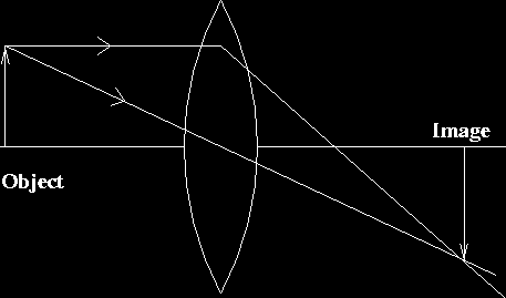
First, we draw a ray parallel to principal axis. So, it passes through focus after refraction. We draw another ray which passes through Optical Center. So, the ray will go through without any deviation. Where both rays meet is point A'. And the image formed is A'B'. This image is formed between F 2 and 2F 2. We can say that.
Ray Diagrams By constructing a ray diagram, we can determine where the image is located, and what it will look like. A ray diagram is a diagram showing rays that can be drawn to determine the size and location of an image formed by a mirror or lens.
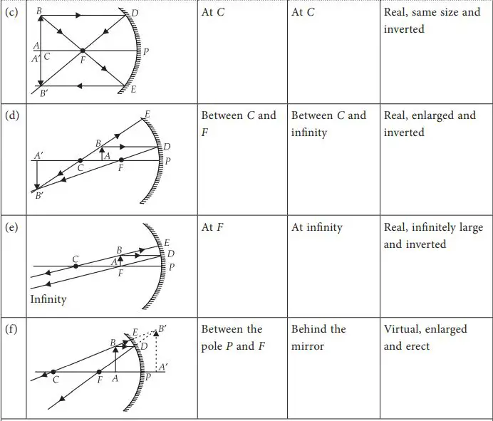
Concave Mirror Ray Diagram lets us understand that, when an object is placed at infinity, a real image is formed at the focus. The size of the image is much smaller compared to that of the object. When an object is placed behind the center of curvature, a real image is formed between the center of curvature and focus.
Diverging mirrors, sometimes refered to as "shoplifting mirrors," only form reduced, virtual images.As can be seen in this diagram below, the incident rays (yellow) all begin on the top of the object (red arrow) and are each scattered from the mirror's front, convex surface.The reflections when dotted back (green lines) form a virtual image (gray arrow) behind the mirror.
Plane mirror- Definition, Properties and Ray Diagram. Mirrors are defined as one side-polished surface that can reflect the light rays. Plane mirrors in physics are the ones that have a flat reflecting surface and produce always a virtual image. In this tutorial, we review the most important topics in the plane (flat) mirrors in physics ...
•A convex mirror is sometimes called a diverging mirror. •The rays from any point on the object diverge after reflection as though they were coming from some ... Ray Diagram for a Concave Mirror, p < f •The object is between the mirror and the focal point. •The image is virtual. •The image is upright.












0 Response to "37 diverging mirror ray diagram"
Post a Comment