39 derive the state table and state diagram for the sequential circuit
Next-State Truth Tables. The next step in our journey toward designing the logic for this system is to take the information we have in the state diagram and turn it into a truth table. Just like all of our previous truth tables, the left-hand columns are going to be for our inputs and the right-hand columns are going to be for outputs. 2 9-3 Sequential Circuits Consist of a combinational circuit to which storage elements are connected to form a feedback path Specified by a time sequence of inputs, outputs, and internal states Two types of sequential circuits: Synchronous Asynchronous primary difference 9-4 Synchronous vs. Asynchronous Asynchronous sequential circuits Internal states can change at any
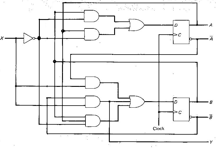
Derive the state table and state diagram for the sequential circuit shown in Figure 7. Figure 7. Logic schematic of a sequential circuit. STEP 1 : First we derive the Boolean expressions for the inputs of each flip-flops in the schematic, in terms of external input Cnt and the flip-flop outputs Q 1 and Q 0.

Derive the state table and state diagram for the sequential circuit
10 Elec 326 19 Sequential Circuit Analysis Derive the state table from the transition table: Where 00 = A, 01 = B, 10 = C, 11 = D Derive the state diagram from the state table: Q X=0 X=1 AA B0 BB D0 CC A1 DD C1 Q* Z Elec 326 20 Sequential Circuit Analysis 4. Synchronous Sequential Circuits & Verilog Blocking vs. non-blocking assignment statements This problem has been solved! (a) Derive a state table and state diagram for the sequential circuit shown below. (b) Create an FSM based on the truth table. (c) Write out the next state equations from the truth table on the previous slide. (d) Draw your circuit using d flip-flops based on the FSM, next state equations, and/or truth table, and ... different output sequence Sequential Circuit and State Machine 2 • Example: - A very simple machine to remember which building I am at - The only input is the clock signal - The state machine is represented as a state transition diagram (or called state diagram) below - One step (i.e., transition) can be taken whenever there is a ...
Derive the state table and state diagram for the sequential circuit. Q.5.20: Design the sequential circuit specified by the state diagram of Fig. 5.19 using T flip-flopsPlease subscribe to my channel. Wish you success,Dhiman K... State Diagrams and State Table Examples. Example 1; In a circuit having input pulses x 1 and x 2 the output z is said to be a pulse occurring with the first x 2 pulse immediately following an x 1 pulse. State Table: Alternatively: Example 2; A pulsed sequential circuit has two input pulses x 1, x 2 and a single output Z. Sequential Circuit Analysis - From sequential circuit to state transition diagrams. Question 1: Design the sequential circuit specified by the state diagram of the figure below, using D flip-flops. a) Derive the state table. b) Derive the flip-flop state and the input equations. c) Draw the logic diagram of the circuit using D flip-flops and externals gates.
(12 Points) For the sequential circuit in Figure 3, derive the state table and the state diagram. Note that for this circuit the outputs are 𝑄 ? and 𝑄 ? Figure 3 – Modulo-3 counter This is a Moore machine because the output is the present state values. A sequential circuit has one flip-flop Q, two inputs x and y, and one output S. It consists of a full-adder circuit connected to a D flip-flop, as shown. Derive the state table and state diagram of the sequential circuit. Solution: FA Q Q SET CLR D X Y S C CLK On this channel you can get education and knowledge for general issues and topics 4. Derive the state table and the state diagram of the sequential circuit shown below. Obtain the output and state sequence with the input sequence: 0110111010. 21 D ) D Q 21 y2 V2: te qe clk 22 ; Question: 4. Derive the state table and the state diagram of the sequential circuit shown below.
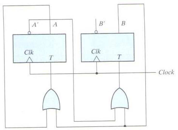
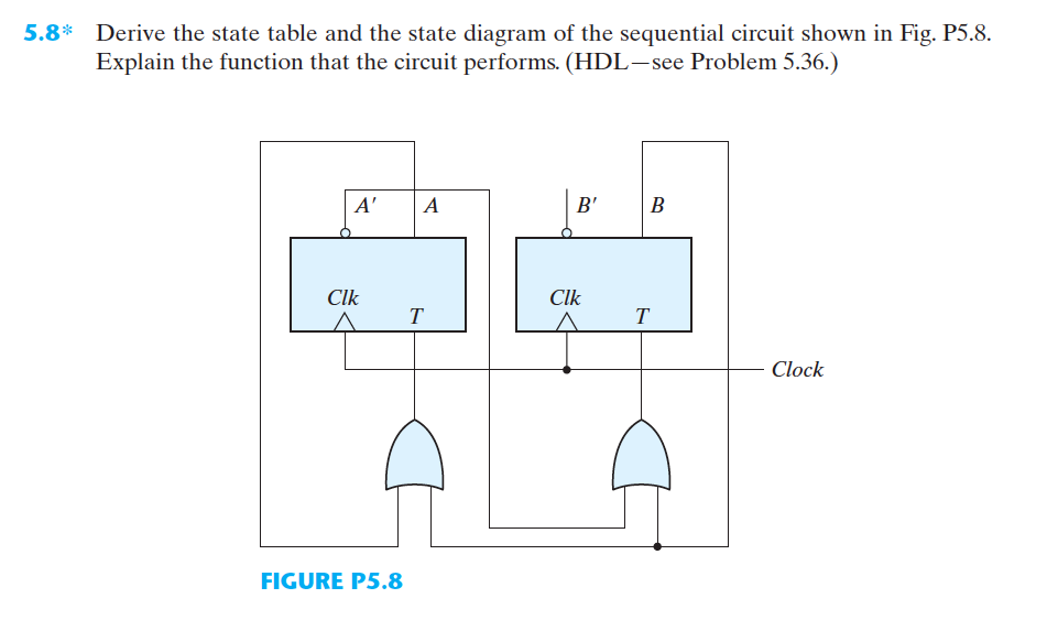
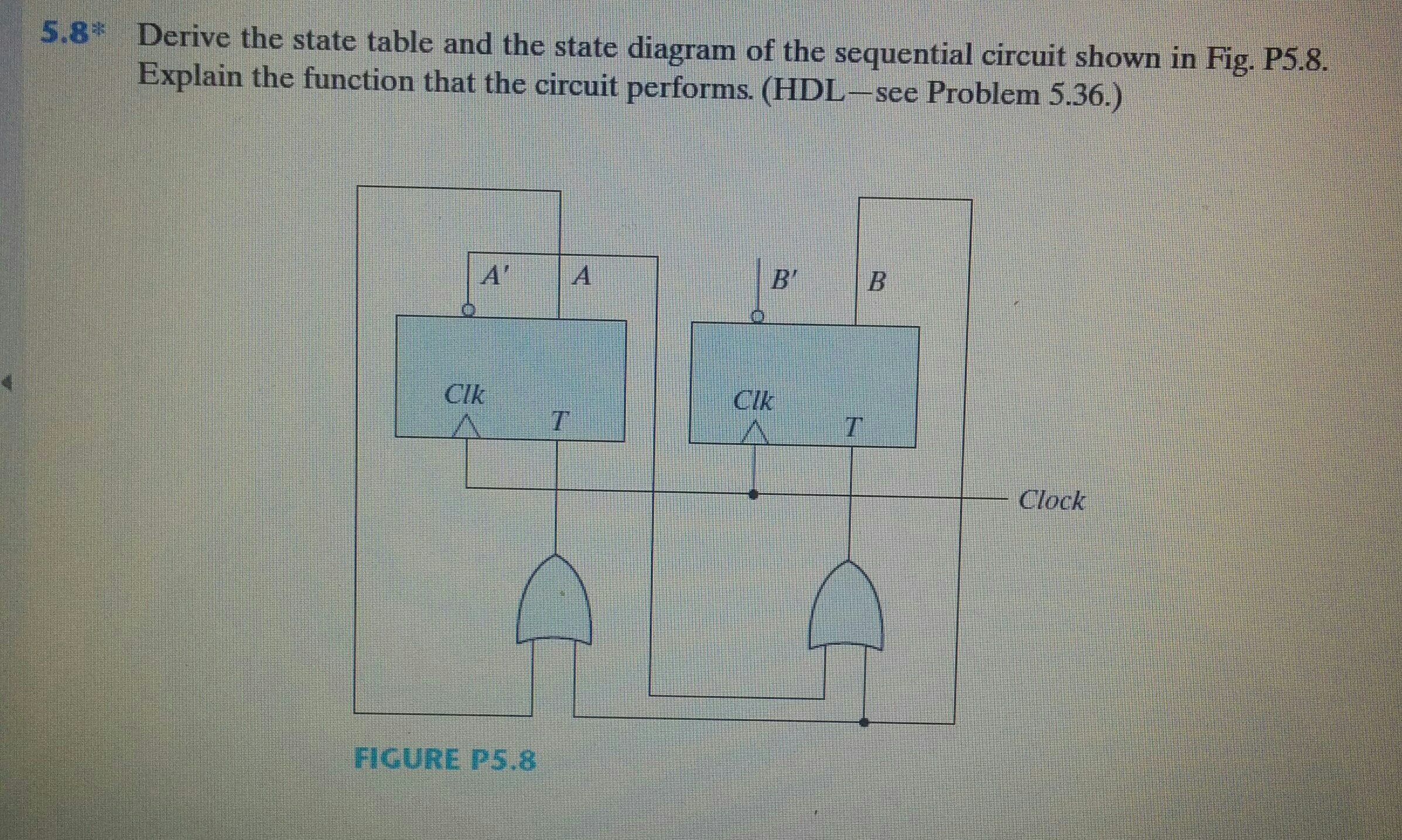
Q. 5.8: Derive the state table and the state diagram of the sequential circuit shown in Fig. P5.8. Explain the function that the circuit performs.Please subs... Circuit, State Diagram, State Table. State: flip-flop output combination Present state: before clock Next state: after clock State transition <= clock 1 flip-flop => 2 states 2 flip-flops => 4 states 3 flip3 flip-flops => 8 statesflops => 8 states 4 flip-flops => 16 states. Sequential circuit components: Page | 3 Problem 3: A sequential circuit with two D flip-flops, A and B; two inputs, x and y; and one output, Z, is specified by the following next-state and output equations: A (t + 1) = x 'y + xA B (t + 1) = x' B + xA z = B (a) Draw the logic diagram of the circuit. (b) Derive the state table. (c) Derive the state diagram. Solution Transcribed image text: Given the sequential circuit below, derive the excitation table. BO S Q' FF1 X- Emphasis RO FF2 What is the next state value AB if the value of A=0,B=1 and C=0 O 11 O 00 10 O 01 Question 4 1 pts Given the sequential circuit below, derive the excitation table.

30 State Table And State Diagram - Wiring Diagram List
February 13, 2012 ECE 152A - Digital Design Principles 6 Reading Assignment Brown and Vranesic (cont) 8 Synchronous Sequential Circuits (cont) 8.2 State-Assignment Problem One-Hot Encoding 8.7 Design of a Counter Using the Sequential Circuit Approach 8.7.1 State Diagram and State Table for Modulo-8 Counter 8.7.2 State Assignment 8.7.3 Implementation Using D-Type Flip-Flops

digital logic - Finding the State Table for a Synchronous ...
b) Derive the state table c) Derive the state diagram Exo_8: Design a sequential circuit with two D flip flops, and two inputs, E and x. If E =0, the circuit remains in the same state regardless of the value of x. When E = 1 and x = 1, the circuit goes through the state transitions from 00 to 01 to 10 back to 00, and repeats. When E = 1 and
Solved: (a) Derive the state graph and table for a Mealy ...
Once the state diagram of the sequential circuit is defined, a Next-State Table is derived which lists each present state and the corresponding next state. The next state is the
Solved: For The Following Counters A And B: Draw The State ...
The state diagram is the pictorial representation of the behavior of sequential circuits. It clearly shows the transition of states from the present state to the next state and output for a corresponding input. 1. In this diagram, each present state is represented inside a circle. 2. The transition from the present state to the next state is represented by a directed line connecting the circles. 3. If the directed line connects the circle itself, which indicates that there is no change in the state(the next state is the same as the present state). 4. For mealy model, the directed line is labeled with binary numbers separated with ‘/’, as shown in the below diagram. 5. The input value, which causes the transition to occur is labeled first ‘1/’. The output produced for the corresponding input is labeled second ‘/0’. 1. For Moore circuit, the directed lines are labeled with only one binary number. It is nothing but the input value which causes the transition. 2. The output value is ind...
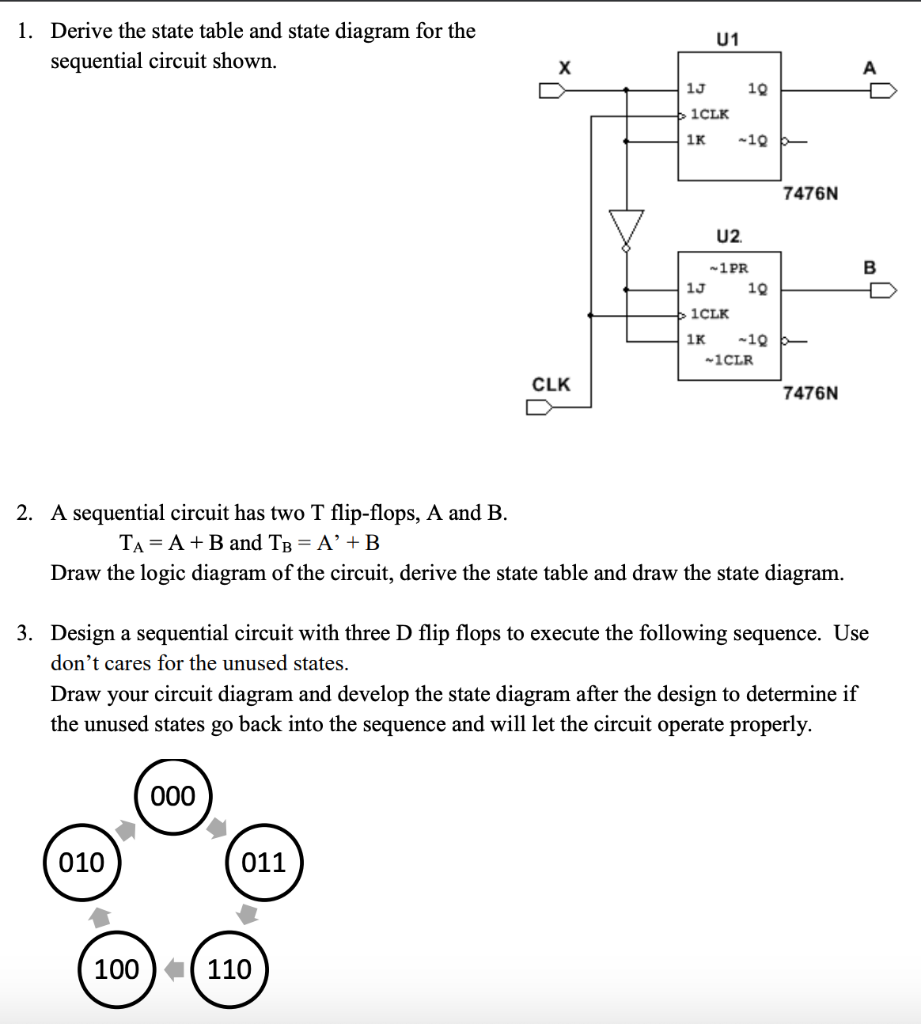
1. Derive the state table and state diagram for the ...
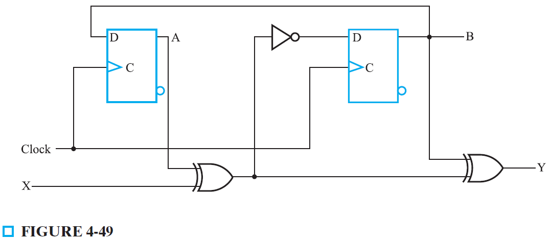
Circuit, State Diagram, State Table Example: state diagram: state diagram = state tablestate table state table/state diagram Îcircuit D-FF characteristic eq: D = Q* 00 01 11 10 00000 AB x D A 00 01 11 10 00000 AB x D B 00 01 11 10 00000 AB x z 10111 11000 10011 D A=Ax+Bx D B=A'B'x z=Ax

Solved: Derive The State Table And State Diagram Of The Se ...
Example 1.4 Design a sequential circuit whose state tables are specified in Table 12, using D flip-flops. Table 12. State table of a sequential circuit. Table 13. Excitation table for a D flip-flop. Next step is to derive the excitation table for the design circuit, which is shown in Table 14. The output of the circuit is labeled Z.
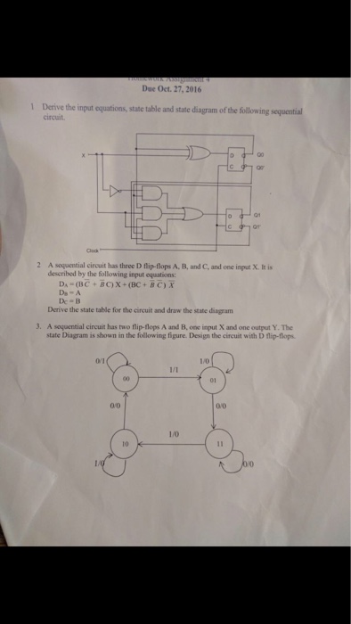
Solved: Derive The Input Equations, State Table And State ...
Sequential circuit components: Flip-flop(s) Clock Logic gates Input Output Circuit, State Diagram, State Table

Solved: Digital Systems Toggle Flip Flops State Diagram An ...
A formal synthesis technique for realizing state tables and diagrams A less formal technique based on transition equations Reading Assignment Sections 3.3 and 3.4. Elec 326 2 Sequential Circuit Design 1. State Table/Diagram Specification There is no algorithmic way to construct the state table from a word description of the circuit. Instead,

Solved: A Sequential Circuit Has Two D Flip-flops,one Inpu ...
1. Obtain the specification of the desired circuit. 2. Derive a state diagram. 3. Derive the corresponding state table. 4. Reduce the number of states if possible. 5. Decide on the number of state variables. 6. Choose the type of flip-flops to be used. 7. Derive the logic expressions needed to implement the circuit.
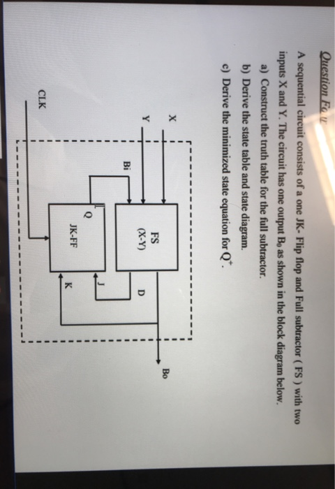
Solved: A Sequential Circuit Consists Of A One JK- Flip Fl ...
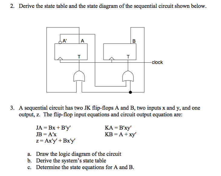
5.8* Derive the state table and the state diagram of the sequential circuit shown in Fig. P5.8 . Explain the function that the circuit performs. (HDL—see Problem 5.36.) 5.9 A sequential circuit has two JK flip-flops A and B and one input x. The circuit is described by the following flip-flop input equations: JA = x KA = B JB = x KB = A

State Table And State Diagram - Hanenhuusholli
Solutions for Chapter 16 Problem 2DP: Design a Mealy sequential circuit (Figure 16-27) which investigates an input sequence X and will produce an output of Z = 1 for any input sequence ending in 1101 or 011. Example: Notice that the circuit does not reset to the start state when an output of Z = 1 occurs.
![Solved: At 5] Analyze The Circuit Below By Finding Its Tra ...](https://media.cheggcdn.com/media%2F39f%2F39f1a310-ea94-411d-a5e7-9164577d8dd5%2Fimage.png)
Solved: At 5] Analyze The Circuit Below By Finding Its Tra ...
5.6) A sequential circuit with two D Flip-Flops, A and B; two inputs, x and y; and one output, z, is specified by the following next-state and output equations: A(t+1) = x′y + xA B(t+1) = x′B + xA z = B a) Draw the logic diagram of the circuit. b) List the state table for the sequential circuit. c) Draw the corresponding state diagram. a)
[Solved] A sequential circuit has two JK Flip-Flops. Given ...
Digital Electronics: Introduction to State Table, State Diagram & State EquationContribute: http://www.nesoacademy.org/donateWebsite http://www.nesoacademy...

Solved: 7. Derive The State Table And State Diagram Of The ...
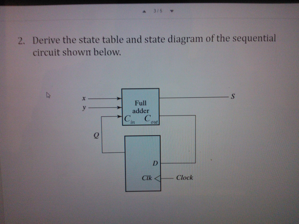
A sequential circuit has one flip-flop Q, two inputs x and y, and one output S. It consists of a full adder circuit connected to a D flip-flop, as shown below. (10 points) Derive the state table and (10 points) state diagram of the sequential circuit.
State Diagram of Sequential circuit - GATE Overflow
•Combinational circuits - output is simply dependent on the current input • Sequential circuits - output may depend on the input sequence • The effect of the input sequence can be memorized as a state of the system Sequential Circuit and State Machine 1 • So a sequential circuit is also called a State Machine • Memory elements (usually D flop -flips) are used to store the

Solved: Use The Finite State Machine (FSM) Methods To Desi ...
State Tables and State Diagrams. We have examined a general model for sequential circuits. In this model the effect of all previous inputs on the outputs is represented by a state of the circuit. Thus, the output of the circuit at any time depends upon its current state and the input. These also determine the next state of the circuit.
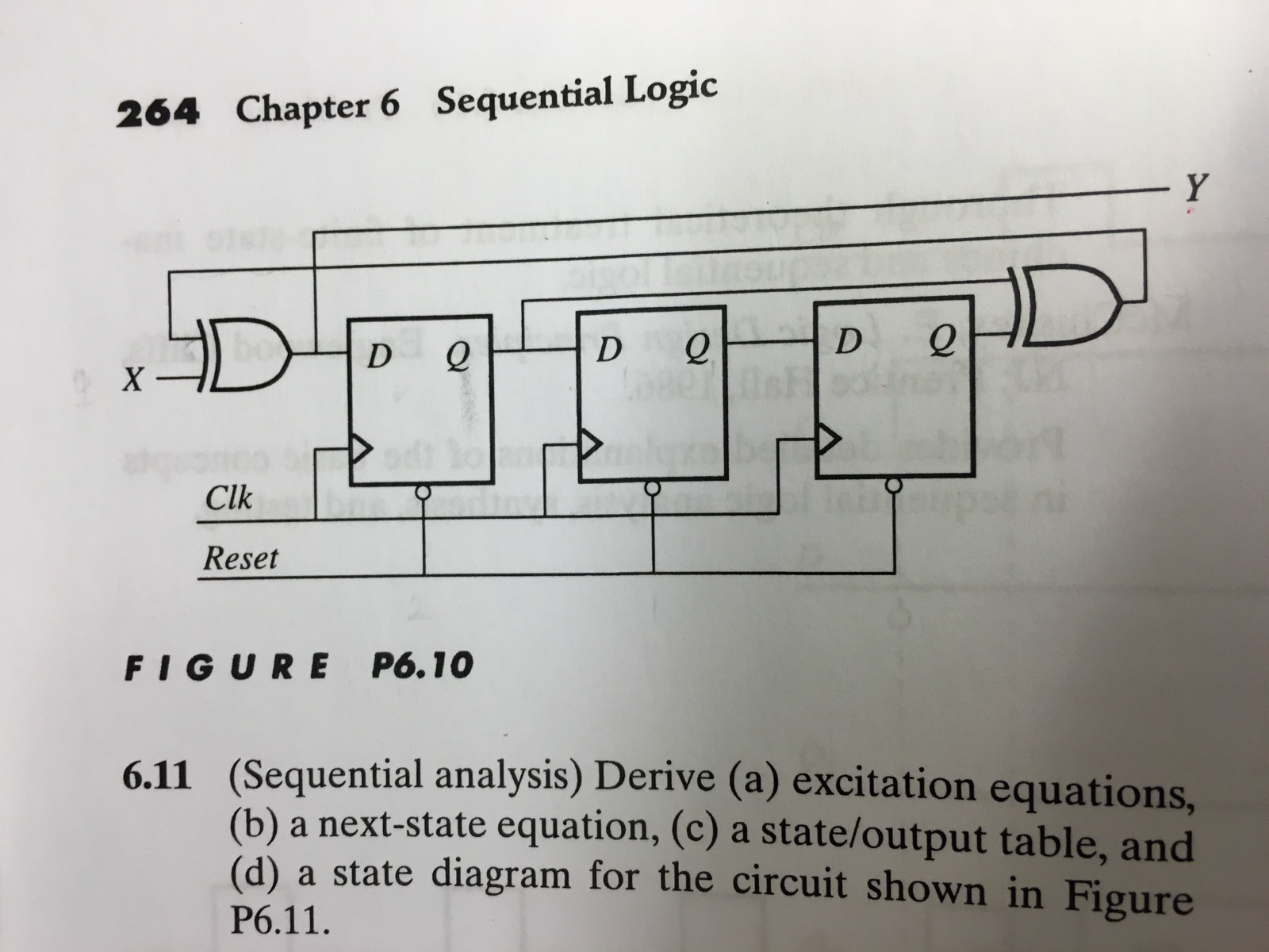
Solved: (Sequential Analysis) Derive (a) Excitation Equati ...
different output sequence Sequential Circuit and State Machine 2 • Example: - A very simple machine to remember which building I am at - The only input is the clock signal - The state machine is represented as a state transition diagram (or called state diagram) below - One step (i.e., transition) can be taken whenever there is a ...

Answered: Derive the state table and the state… | bartleby
This problem has been solved! (a) Derive a state table and state diagram for the sequential circuit shown below. (b) Create an FSM based on the truth table. (c) Write out the next state equations from the truth table on the previous slide. (d) Draw your circuit using d flip-flops based on the FSM, next state equations, and/or truth table, and ...
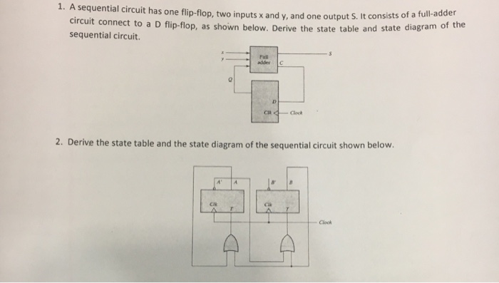
Solved: 1. A Sequential Circuit Has One Flip-flop, Two Inp ...
10 Elec 326 19 Sequential Circuit Analysis Derive the state table from the transition table: Where 00 = A, 01 = B, 10 = C, 11 = D Derive the state diagram from the state table: Q X=0 X=1 AA B0 BB D0 CC A1 DD C1 Q* Z Elec 326 20 Sequential Circuit Analysis 4. Synchronous Sequential Circuits & Verilog Blocking vs. non-blocking assignment statements

Solved: Derive The Input Equations, State Table And State ...
Solved: A Sequential Circuit Has Two D Flip-flops, One Inp ...
Solved: Derive The State Table And The State Diagram Of Th ...

Solved: (a) Derive the state graph and table for a Mealy ...

Derive the state equation, state table and the state ...
Morris Mano Edition 3 Exercise 6 Question 9 (Page No. 253 ...
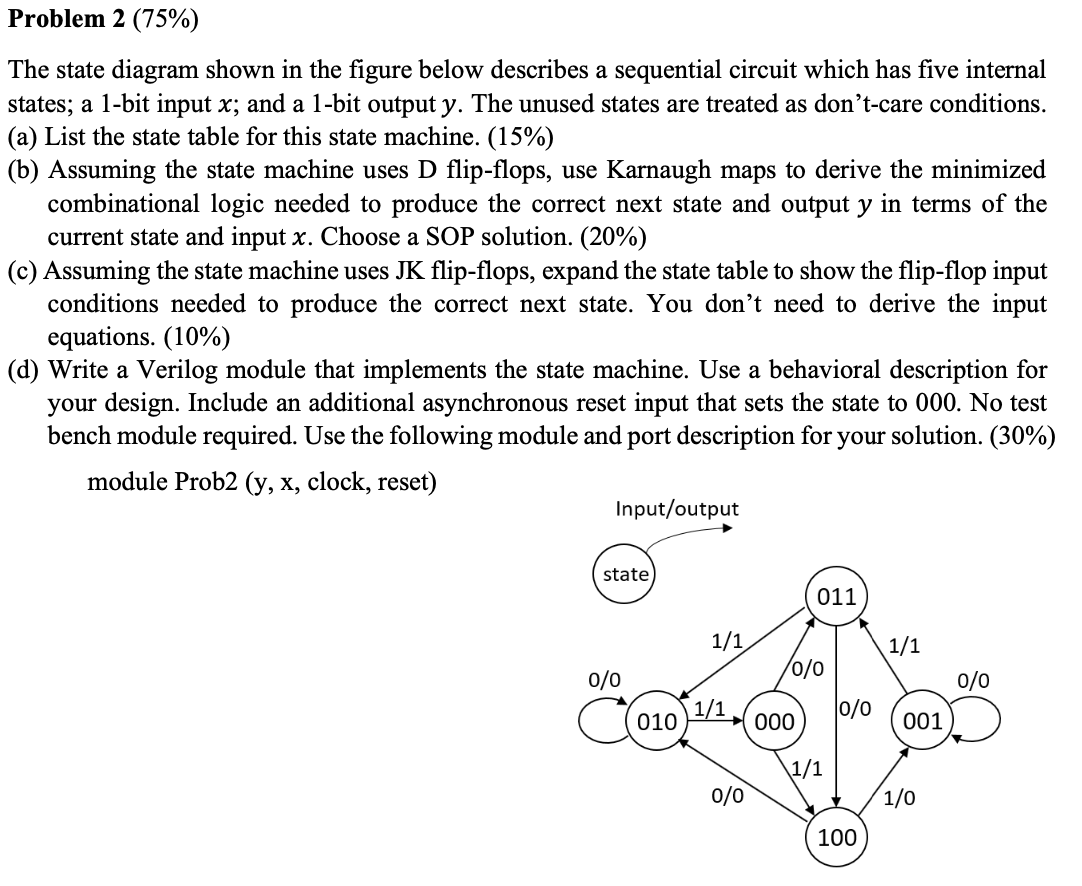
Solved: Problem 2 (75%) The State Diagram Shown In The Fig ...
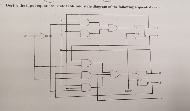
Solved: Derive The Input Equations, State Table And State ...

Lecture 11B: Sequential Circuit Analysis, Next State ...
Solved: Derive The State Table And The State Diagram Of Th ...
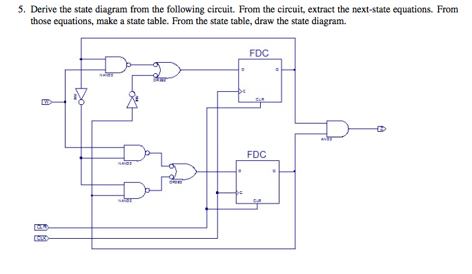
Solved: Derive The State Diagram From The Following Circui ...

Solved: Drive The State Table And The State Diagram Of The ...
[Solved] Derive the state table and the state diagram of ...
Solved: A Sequential Circuit With Two D Flip-flops, A And ...
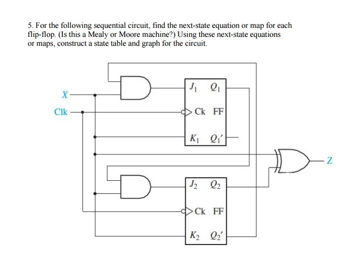
Solved: For The Following Sequential Circuit, Find The Nex ...

State Diagram Of Sequential Circuit Using T Flip Flop ...

Solved: Draw The State Diagram Of The Sequential Circuit S ...
Solved: Derive The State Table And The State Diagram Of Th ...
Solved: Derive The Input Equations, State Table And State ...
Solved: Derive The State Table And State Diagram Of The Se ...
0 Response to "39 derive the state table and state diagram for the sequential circuit"
Post a Comment