39 Bluetooth Transmitter And Receiver Circuit Diagram
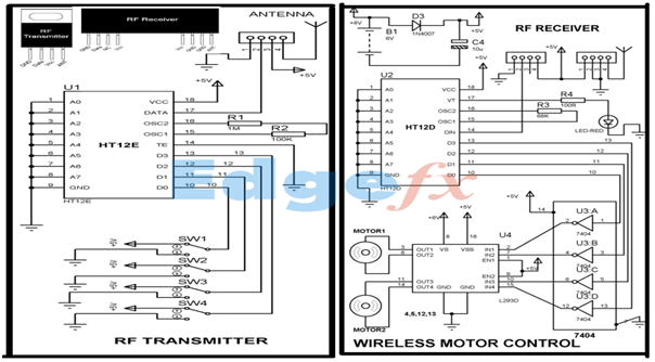
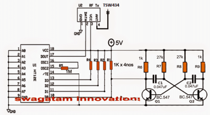
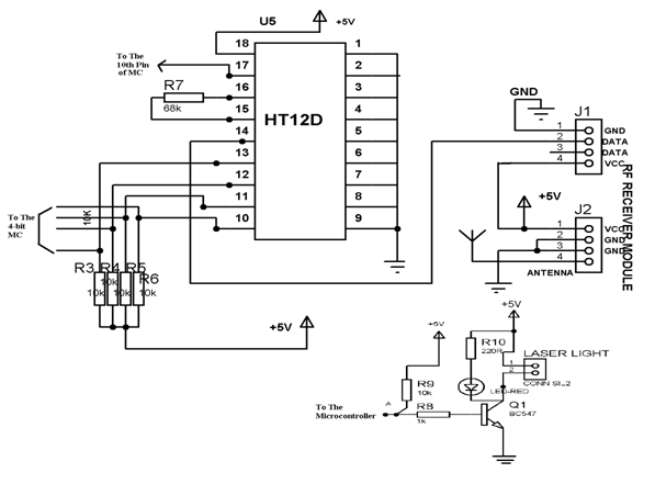
IR Transmitter and Receiver Circuit Diagram 20.8.2015 · IR Transmitter Circuit Diagram. We are using TSOP1738 as IR receiver, so we need to generate the modulated IR of 38 kHz. You can use any TSOP, but you need to generate IR of respective frequency as TSOP. So we are using 555 timer in Astable mode to oscillate the IR at 38KHz frequency. What is RF Transmitter and Receiver: Applications All ... 22.5.2020 · RF Transmitter Circuit Diagram HT12E is an encoder IC that converts the 4-bit parallel data from the 4 data pins into serial data in order to transmit over RF link using transmitter. RF Receiver Circuit Diagram HT12D is a decoder IC that converts the serial data received by the RF Receiver into 4-bit parallel data and drives the output accordingly.
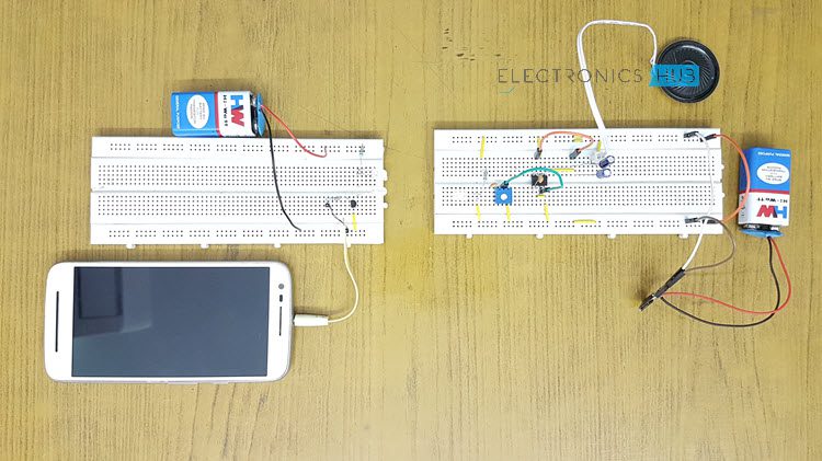
IR Transmitter and Receiver Circuits - Electronics Hub 13.4.2017 · IR Transmitter and Receiver pair form a simple circuit which can be easily built. Can be used for simple remote controlling applications, small data transfer, etc. IR Transmitter and Receiver pair as a module can be used in security applications, proximity sensors, distance measurement applications, etc.

Bluetooth transmitter and receiver circuit diagram
Bluetooth Transmitter User Manual - FCC ID Bluetooth Transmitter User Manual Please read this ... Product Diagram Standard accessories 1.Bluetooth transmitter x1 2.USB charging cable x1 3.3.5mm audio cable x1 ... -- Connect the equipment into an outlet on a circuit different from that to which the receiver is connected. TaoTronics Bluetooth 5.0 Transmitter and Receiver - Manuals+ 31.12.2020 · Contents hide 1 User Manual 2 Package Contents 3 Specifications 4 Product Diagram 5 Control Functions 6 LED Indicators 7 How to Use 8 Pairing 9 Care and Maintenance 10 Bluetooth 11 FCC Compliance 11.1 Related Manuals / Resources User Manual TaoTronics Bluetooth 5.0 Transmitter and ReceiverWireless 2-in-1 Adapter, Model: TT-BA07 NORTH … Arduino LoRa Communication - Transmitter & Receiver Setup ... 26.9.2019 · Circuit Diagram. Circuit diagrams for LoRa transmitting and receiving side are given below. In this project, we are going to send temperature and humidity values from one Arduino to another using LoRa SX1278 module. The DHT11 sensor is …
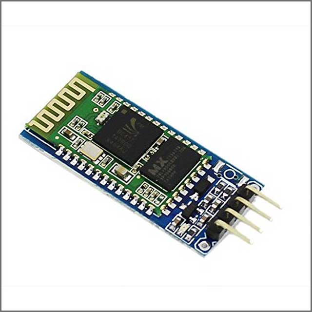
Bluetooth transmitter and receiver circuit diagram. Wireless RF Module | RF Transmitter and Receiver | Latest ... RF Transmitter Circuit: RF Transmitter Circuit RF Receiver Circuit: RF Receiver Circuit. 2. XBee Module: What is the XBee Module? XBee modules are wireless communication modules that are built based on the Zigbee standard. It utilizes the IEEE 802.15.4 protocol. Zigbee standards are standards with a range between Bluetooth and WIFI. RF Transmitter and Receiver Circuit Diagram 25.8.2017 · As you can see the RF Transmitter Circuit consists of the Encoder IC and RF Receiver circuit consists of the Decoder IC.Since the transmitter does not need a regulated 5V we have directly powered it with a 9V battery. Whereas in the receiver side we have used a 7805 +5V voltage regulator to regulate 5V from the 9V battery. 433MHz RF Receiver Pinout, Applications, Examples and Features 433MHz RF Receiver Applications. The RF receiver has a vast use in the home automation. In-home security, most of the burglar alarm uses the RF receiver to receive the data. RF module receives the data from remote in the car. Remote keyless entries also use the RF module for receiving the data. How to Configure HC-05 Bluetooth Module As Master and ... How to Configure HC-05 Bluetooth Module As Master and Slave Via AT Command: This tutorial is going to teach you some basics on configuring two HC-05 Bluetooth Modules as Master and Slave respectively and also a simple tutorial to …
Arduino LoRa Communication - Transmitter & Receiver Setup ... 26.9.2019 · Circuit Diagram. Circuit diagrams for LoRa transmitting and receiving side are given below. In this project, we are going to send temperature and humidity values from one Arduino to another using LoRa SX1278 module. The DHT11 sensor is … TaoTronics Bluetooth 5.0 Transmitter and Receiver - Manuals+ 31.12.2020 · Contents hide 1 User Manual 2 Package Contents 3 Specifications 4 Product Diagram 5 Control Functions 6 LED Indicators 7 How to Use 8 Pairing 9 Care and Maintenance 10 Bluetooth 11 FCC Compliance 11.1 Related Manuals / Resources User Manual TaoTronics Bluetooth 5.0 Transmitter and ReceiverWireless 2-in-1 Adapter, Model: TT-BA07 NORTH … Bluetooth Transmitter User Manual - FCC ID Bluetooth Transmitter User Manual Please read this ... Product Diagram Standard accessories 1.Bluetooth transmitter x1 2.USB charging cable x1 3.3.5mm audio cable x1 ... -- Connect the equipment into an outlet on a circuit different from that to which the receiver is connected.
Bluetooth fm transmitter: Simple Fm Transmitter Circuit Diagram
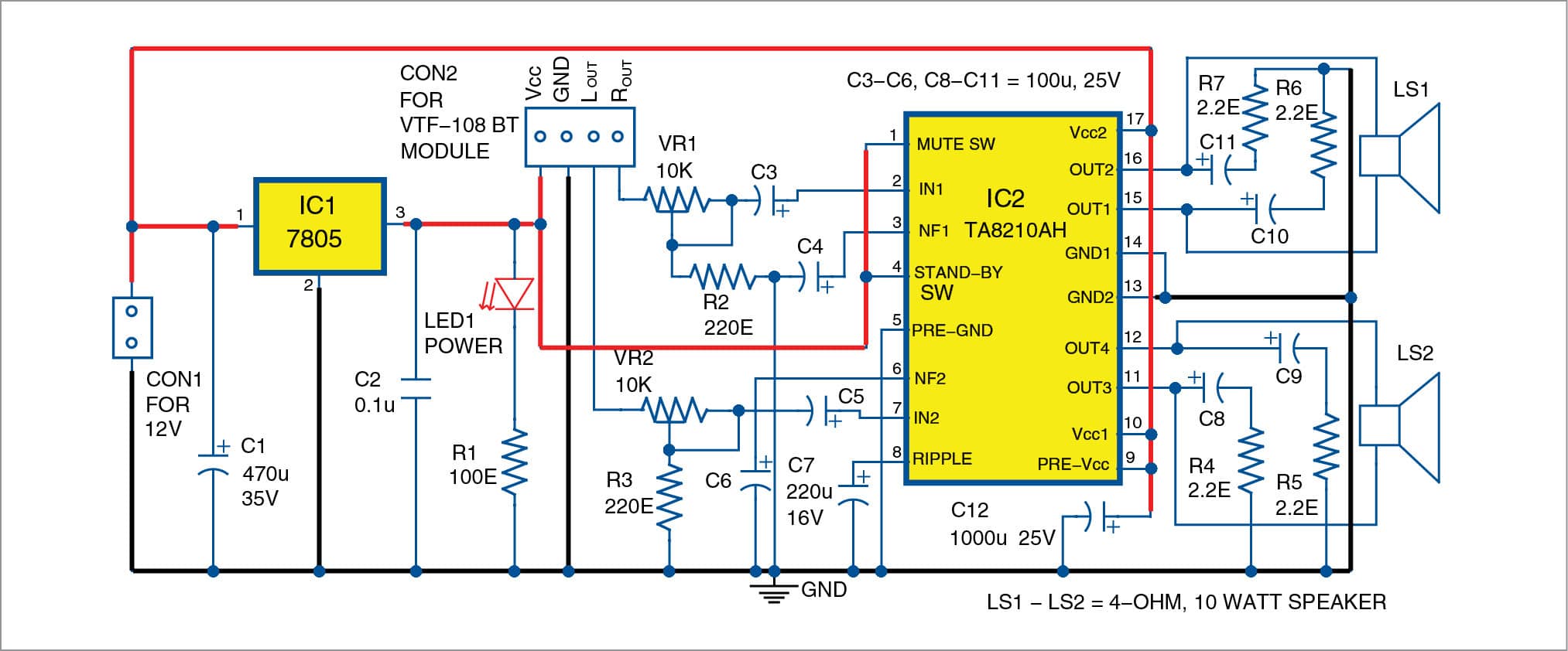
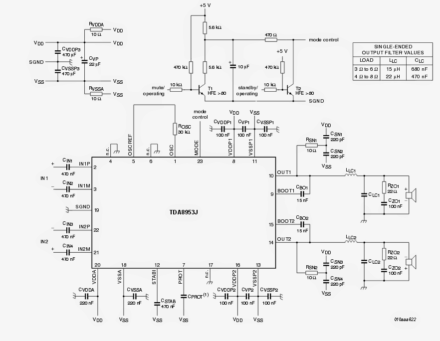
Two-Channel Wireless Audio Amplifier Using Bluetooth and TA8210AH
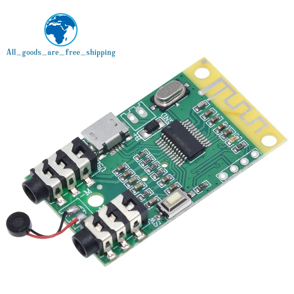
Bluetooth 4.2 audio transmitter receiver board 3.7V~5V 10M ...
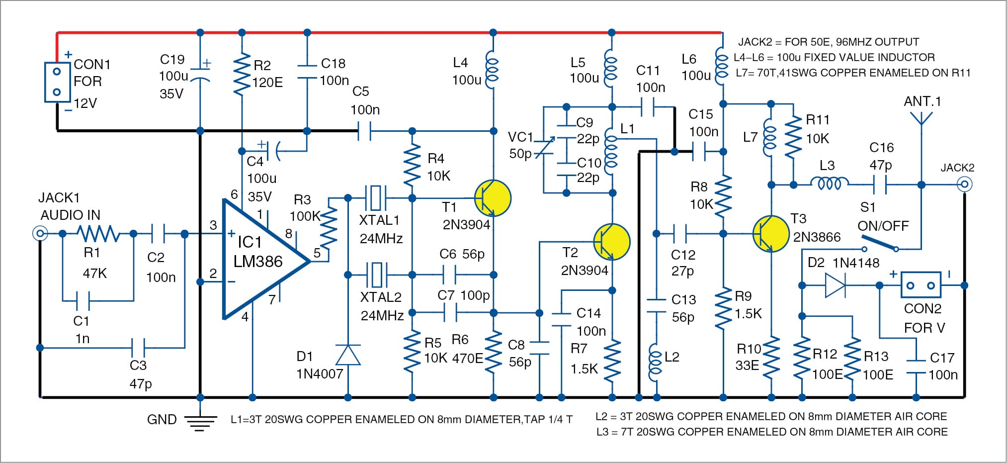
Make A Crystal-Locked FM Transmitter | Full Circuit Project
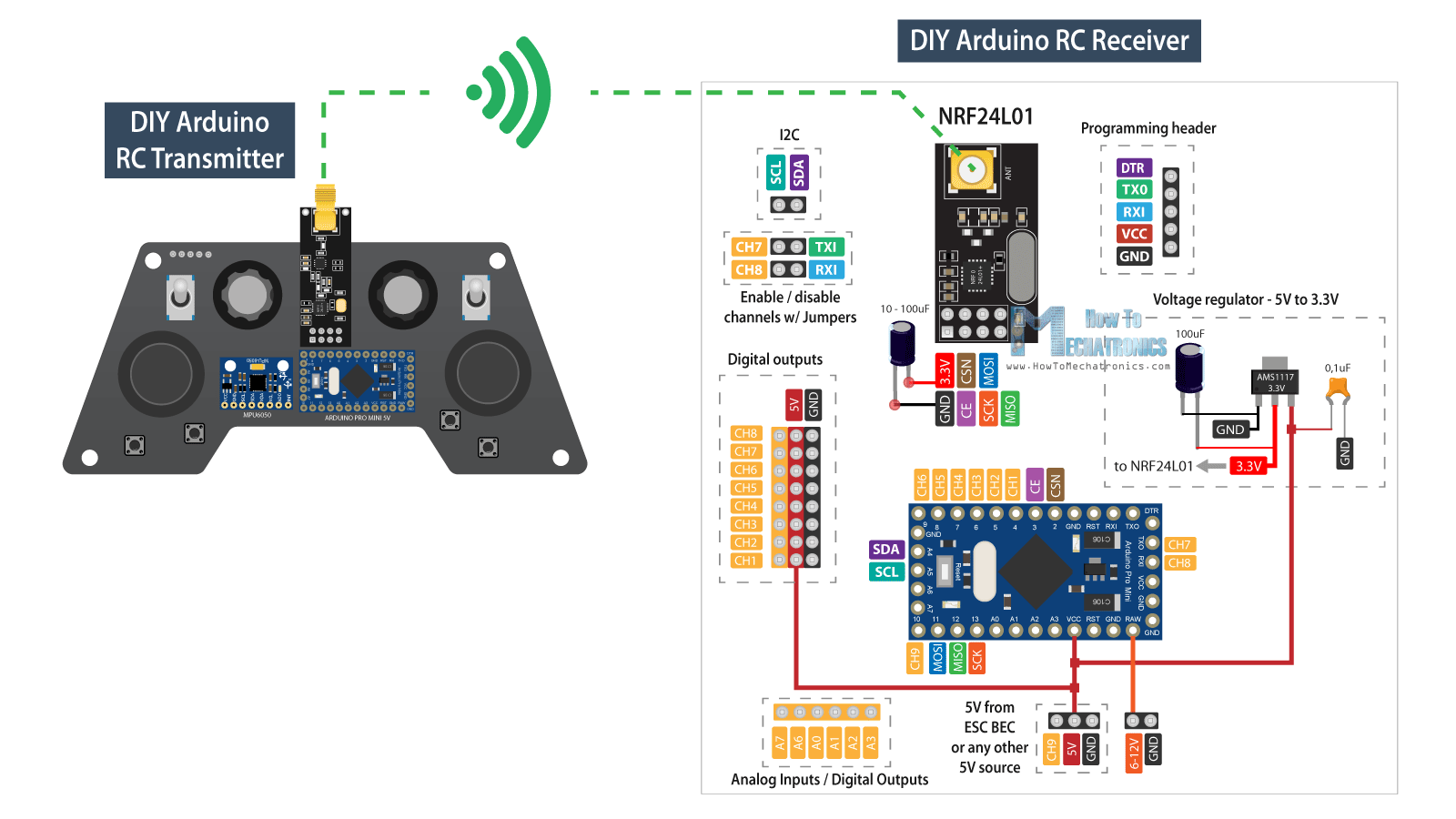
DIY Arduino RC Receiver for RC Models and Arduino Projects

8 Bluetooth circuit diagram ideas | circuit diagram ...
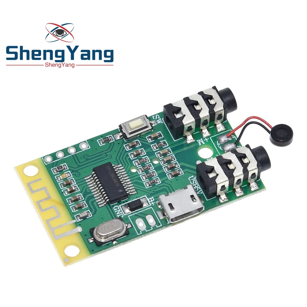
Bluetooth 4.2 audio transmitter receiver board 3.7V~5V 10M ...

Wireless Mobile Charger Circuit Diagram - Engineering Projects

DIY Bluetooth Audio Adapter - BluFi : 9 Steps (with Pictures ...

Amazon.com: Fosi Audio BT30D Bluetooth 5.0 Stereo Audio ...

IR Transmitter and Receiver Circuit Diagram
Bluetooth Circuit Board-How To Count As a High-Quality ...

Make Your Own Low Budget Bluetooth Music System : 5 Steps ...

RF Transmitter and Receiver Circuit Diagram
Wireless RF Module | RF Transmitter and Receiver | Latest ...

Amazon.com: Blue~Tooth Board, DROK Portable Wire~Less Blue ...

Details about Bluetooth Audio Receiver mini Module - Stereo Output - 5V DC Operation USA
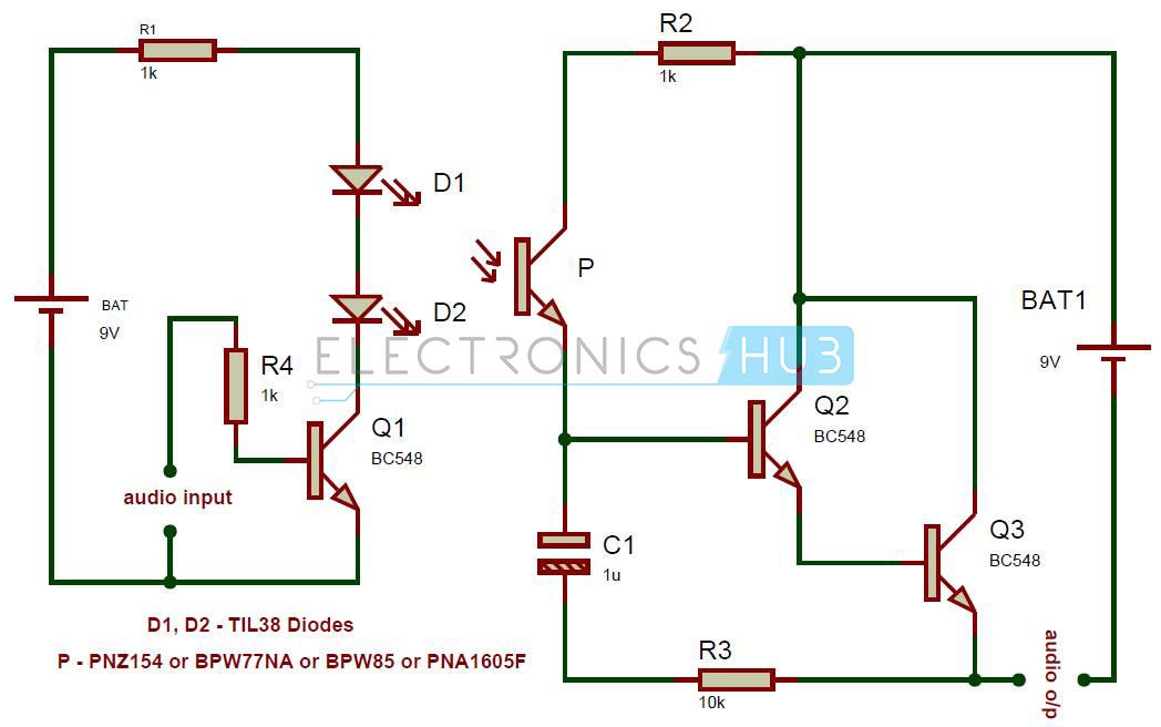
Simple IR Audio Transmitter and Receiver Circuit

2.4 GHz, 0.25 mm CMOS Transmitter and Receiver RFICs for ...
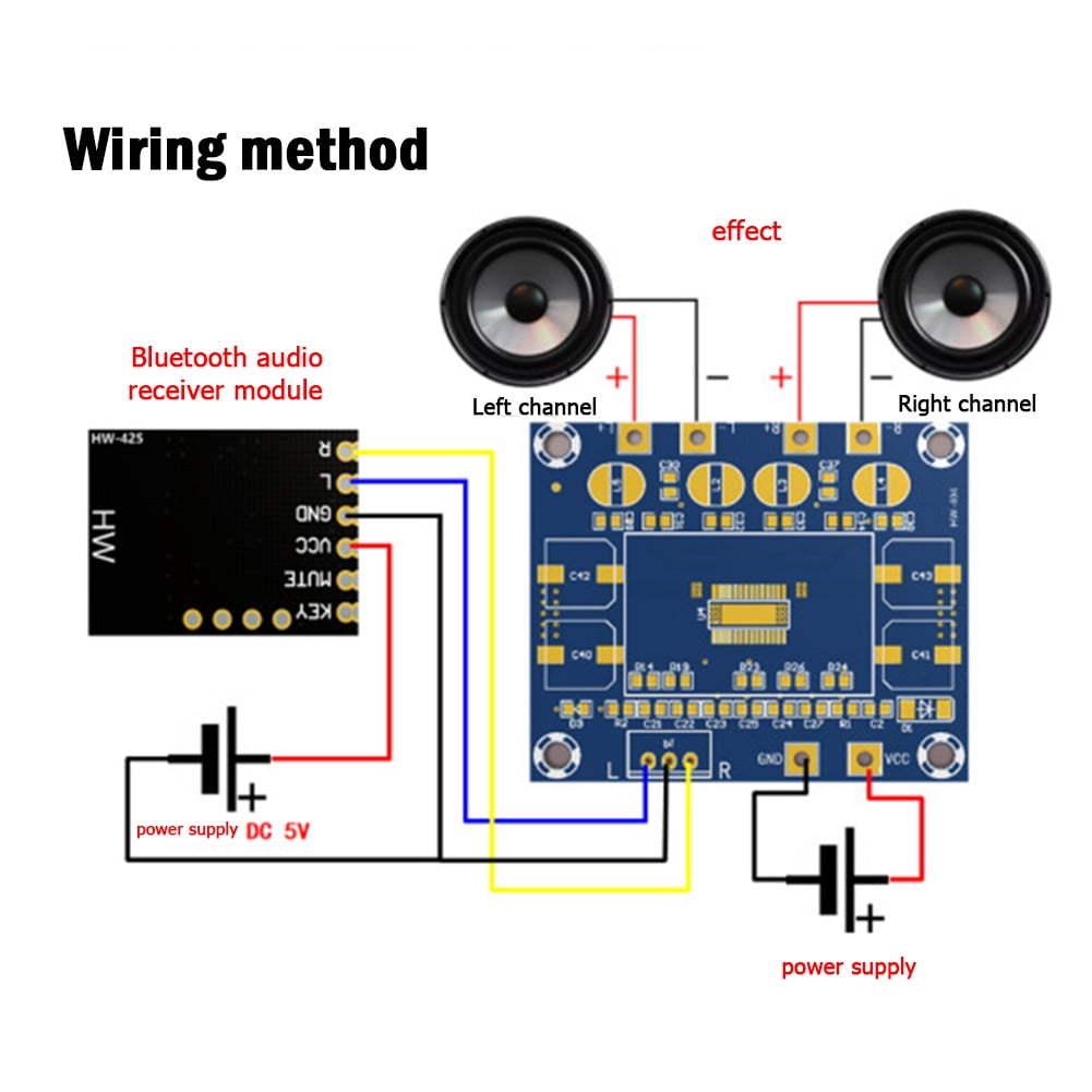
C&P HW-425 Bluetooth-compatible 4.2 Audio Receiver Module ...

Planet Analog - Design for a Radio-Controlled Car
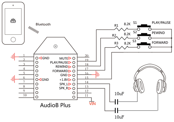
AudioB Plus Bluetooth Audio Receiver Module
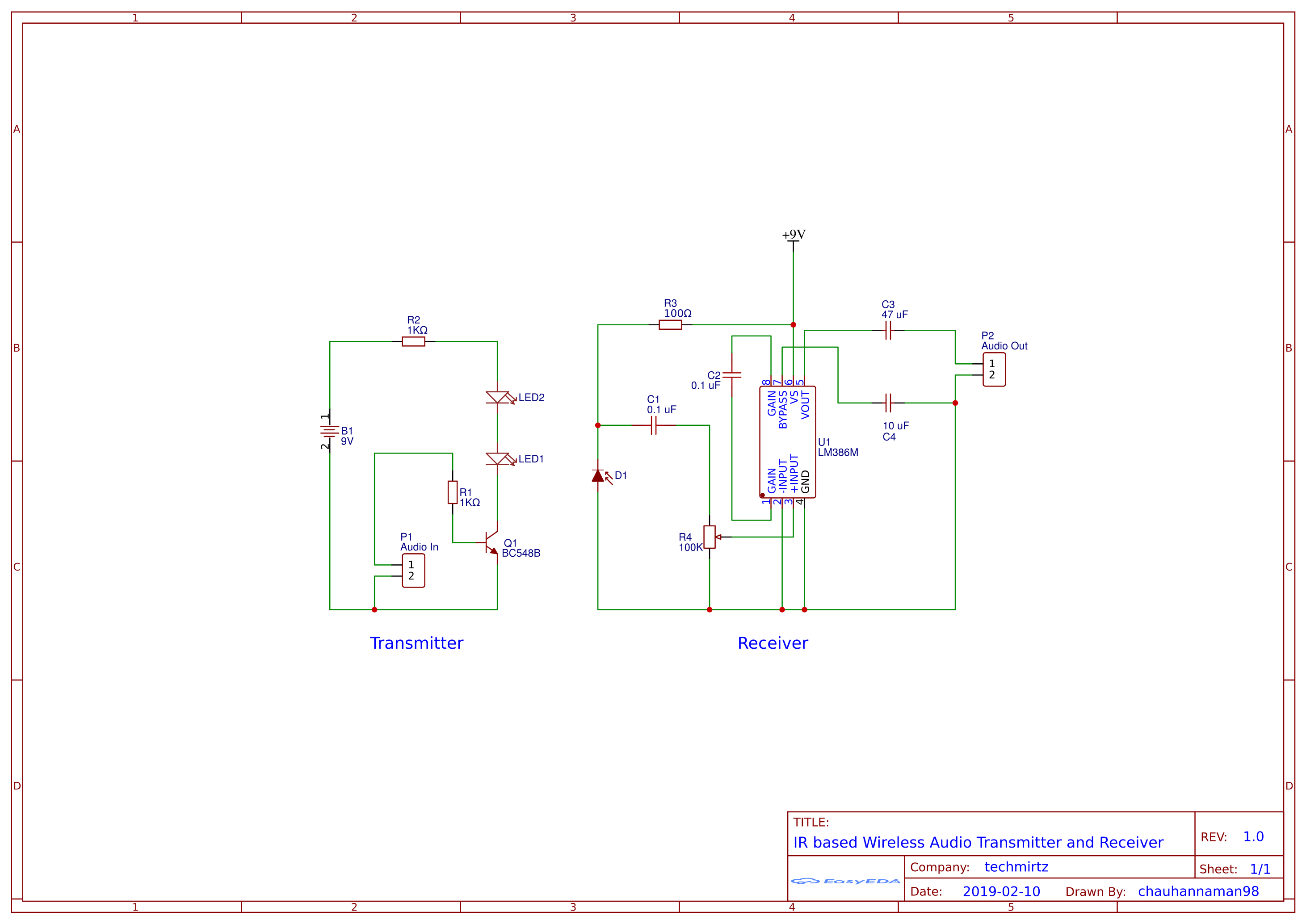
IR-Based Wireless Audio Transmitter and Receiver - Hackster.io
Key Finder or Pet Tracker Circuit - Homemade Circuit Projects

Linear Actuator Long Range Wireless Control System using ...
Simulink block diagram of Bluetooth transmitter and receiver ...
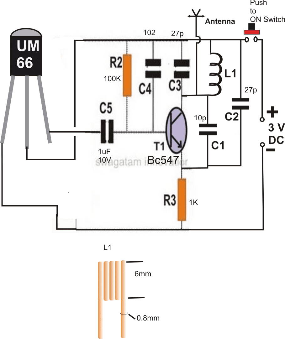
Remote Control Circuit Using FM Radio - Homemade Circuit Projects

DA-8300BB Bluetooth Music Receiver Schematics Circuit ...
Wireless Home theater Circuit using Bluetooth Headset ...

Make Simple FM Receiver

Simple RF Remote Control Circuit without Microcontroller ( No ...

8 Bluetooth circuit diagram ideas | circuit diagram ...
Wireless RF Module | RF Transmitter and Receiver | Latest ...
![TJH] nRF52832 2.4GHz Transceiver Wireless RF Module Receiver ...](https://zoodmall.com/cdn-cgi/image/w=450,fit=contain,f=auto/http://picture.irobotbox.com/public/1312/ProductImages/11845183/2019/06/10/531683c45128433f9fbf58590154ef3a/65599157-3932-44e7-8950-bdd5a1c35924.jpg)
TJH] nRF52832 2.4GHz Transceiver Wireless RF Module Receiver ...
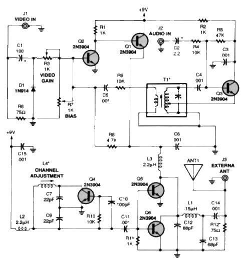
TV audio video transmitter circuit design project under ...
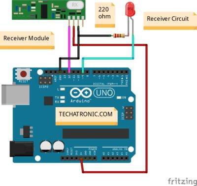
Arduino with Rf module Interfacing | Rf module with Arduino

DIY Bluetooth Audio Adapter - BluFi : 9 Steps (with Pictures ...
Simple IR Audio Transmitter and Receiver Circuit
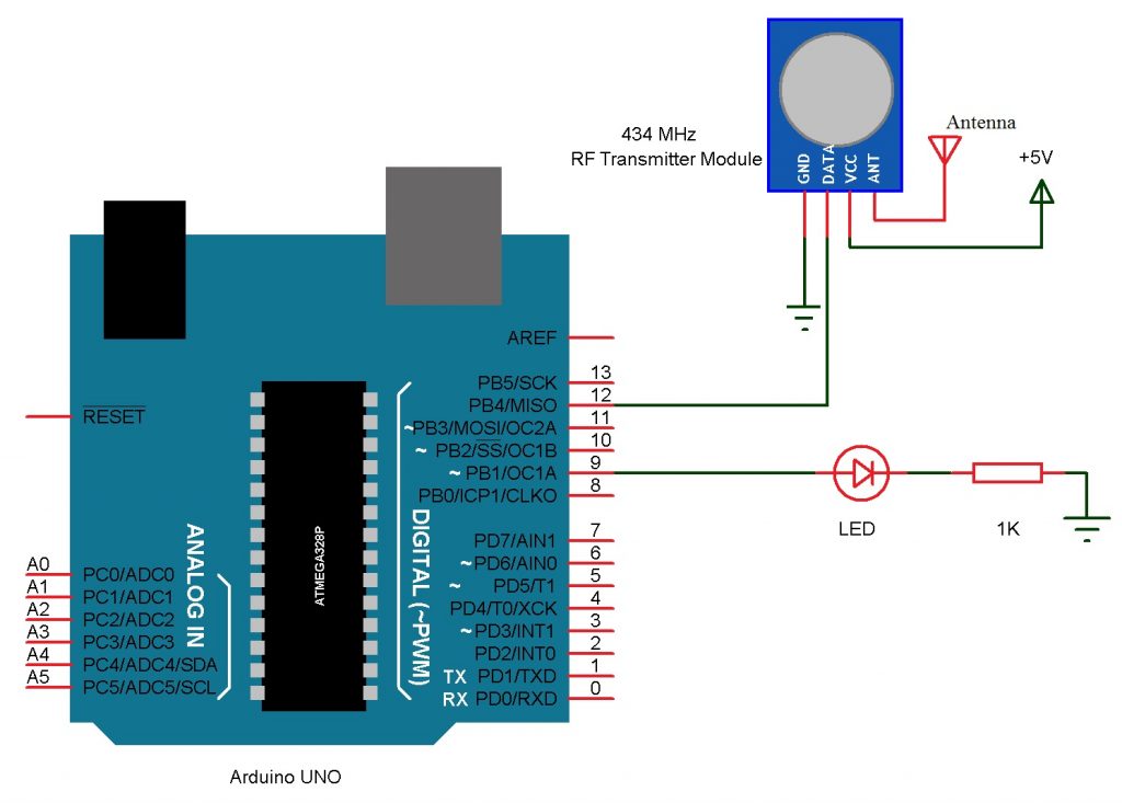
Arduino and RF Transmitter Receiver Module
0 Response to "39 Bluetooth Transmitter And Receiver Circuit Diagram"
Post a Comment