39 the diagram shows the cross section of a wire
The diagram shows a battery, a fixed resistor, an ammeter and a variable resistor connected in series. mm A voltmeter is connected across the fixed resistor. A copper wire of cross-sectional area 2.0 V A The value of the variable resistor is reduced. Which correctly describes the changes in the readi ngs of the ammeter and of the voltmeter? (b)€€€€ A length of steel wire and a length of brass wire are joined together. This combination is suspended from a fixed support and a force of 80 N is applied at the bottom end, as shown in the figure below. Each wire has a cross-sectional area of 2.4 × 10⁻⁶ m2. length of the steel wire = 0.80 m length of the brass wire = 1.40 m
Q10 The diagram below shows the cross section of a wire which is perpendicular to the page and a uniform magnetic field directed to the right. Toward which point should the wire be moved to induce the maximum electric potential?
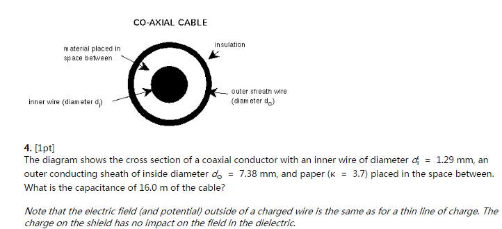
The diagram shows the cross section of a wire
Apr 01, 2010 · Wire between two magnets. The diagram shows a straight wire carrying a flow of electrons out of the page. The wire is between the poles of the permanent magnet. The direction of the magnetic force exerted on the wire is: Please Note: My diagram isn't perfect but both magnets are the same size and the wire is equidistant from both of the magnets. The diagram shows a conical section fabricated from pure aluminum. The end temperatures are t 1 600k and t 2 400k while the lateral surface is well insulated. The small end is located at and the large end at. Sketch the temperature distribution. It is of circular cross section having diameter d ax12 where a 05m12. magnitude 25N and acts at an angle of 15 to the horizontal, as shown in the diagram. Find (i) the work done by the pulling force in moving the crate a distance of 2m, [2] (ii) the normal component of the contact force on the crate. [3] 4 The diagram shows a vertical cross-section of a surface. A and B are two points on the cross-section.
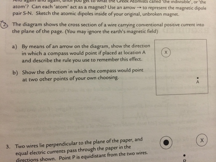
The diagram shows the cross section of a wire. The diagram shows two wires, P and Q, of equal length, joined in series with a cell. A voltmeter is connected between the end of Q and a point X on the wires. The p.d. across the cell is V. Wire Q has twice the area of cross-section and twice the resistivity of wire P. The variation of the The diagram shows the cross-section of a wire, with current flowing into the direction of the page Draw the magnetic field (shape and direction around the wire A current (of 25A flows through a coil of wire 30mm long. The collhas 200 tums Calculate the magnetomotive force (mm) the magnetic field strength (magnetising force) C. ... The diagram shows the cross section of wire carrying conventional positive current into the plane of the page. (You may ignore the earth's magnetic field) A) By means of an arrow on the diagram, show the direction in which a compass would point if placed at location A and describe the rule you use to remember this effect. B) Show the direction in which the compass would point at two other points of your own choosing. Here is the question and accompanying diagram: The diagram above shows two wires; wire 1 and wire 2. The charge carriers in wire 1 (of circular cross section and radius R) have a drift speed down the wire that is not constant across the wire.
6. Each diagram shows a cross-section through two parallel conductors, each carrying an electric current. 7. In the conductor on the left, the current is into the page; on the right, it is out of the page. 8. Which diagram shows the directions of the forces on the two conductors? Electromagnetism 42 C 43. 7. represented in the diagram. What is the direction of the magnetic field above the wire at point P? (1) into the page (2) out of the page (3) toward the top of the page (4) toward the bottom of the page 17. Each diagram below represents a cross section of a long, straight, current-carrying wire with the electron flow into the page. Which diagram The diagram shows two wires, P and Q, of equal length, joined in series with a cell. A voltmeter is connected between the end of Q and a point X on the wires. The p.d. across the cell is V. Wire Q has twice the area of cross-section and twice the resistivity of wire P. The variation Sep 28, 2007 · Homework Statement. The diagram shows two wires; wire 1 and wire 2. The charge carriers in wire 1 (of circular cross section and radius R) have a drift speed down the wire that is not constant across the wire. Instead, the drift speed rises linearly from zero at the circumference (r=R) to at the center (r = 0), according to vd1 (r)=Vo (1- (r/R)).The second wire (wire 2) has the same radius, the same density of charge carriers and a constant drift speed given by vd1 (r)= fVo.
25 The diagram shows the shape of the magnetic field lines near a current-carrying conductor. conductor P Q The current in the conductor is into the plane of the diagram. Which row correctly states the direction of the field lines and compares the strengths of the field at points P and Q? direction of field lines the field is stronger at May 30, 2012 · (b) The diagram shows a cross-section through a wire placed between two magnetic poles. The wire carries electric current into the page at X. The shape of the magnetic field is shown. (i) Add arrows to any two lines to show the direction of the magnetic field. (1) (ii) Draw an arrow on the diagram to show the direction of the force on the wire. The diagram shows the cross section of wire carrying conventional positive current into the plane of the page. The strength of these fields varies directly with the size of the current flowing through the wire and inversely to the distance from the wire. B show the direction in which the compass would point at the other points of your own choosing. Principle: It is based on the principle that if a wire of uniform area of cross-section carries a constant current, the potential drop across any portion of the wire is directly proportional to the length of that portion of the wire. The diagram is as shown. First, the key K is inserted. This brings the cell of emf E 1 in the circuit. The ...
(b) The diagram below shows the cross-section of a cable consisting of parallel filaments that can be made superconducting, embedded in a cylinder of copper. (i) The cross-sectional area of the copper in the cable is 2.28 × 10 -7. m. 2. The resistance of the copper in a 1.0 m length of the cable is 0.075 Ω. Calculate
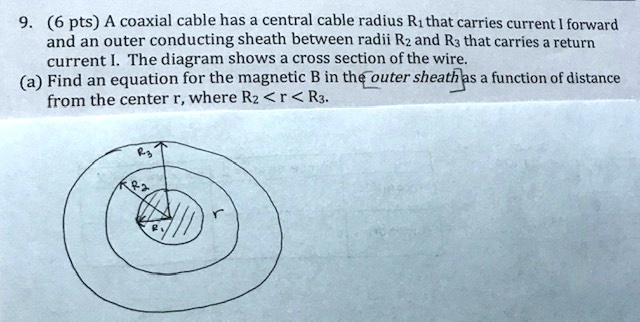
(a) A model of a current-carrying wire of radius a and current (b) A cross-section of the same wire showing the radius a and the Ampère's loop of radius r. Strategy This problem has the same geometry as (Figure) , but the enclosed current changes as we move the integration path from outside the wire to inside the wire, where it doesn't ...
The figure shows a cross section of three parallel wires each carrying a current of 24 The currents in wires B and C are out of the paper, while that in wire A is into the paper If the distance R = 511 mm, what is the magnitude of the force on a 40-m length of wire A? b. 15 77 59 mN 12 32 mN Along cylindrical wire (radius =
(b) The diagram shows a cross-section through a wire placed between two magnetic poles. The wire carries electric current into the page at X. The shape of the magnetic field is shown. (i) Add arrows to any two lines to show the direction of the magnetic field. (1) (ii) Draw an arrow on the diagram to show the direction of the force on the wire.
The diagram shows three pairs of parallel wires with the currents in the directions shown. ... Each of the diagrams below is a cross-section through two parallel current-carrying conductors. ... An alternating current is passed through a wire stretched between the poles of a magnet. Which way will the wire move?
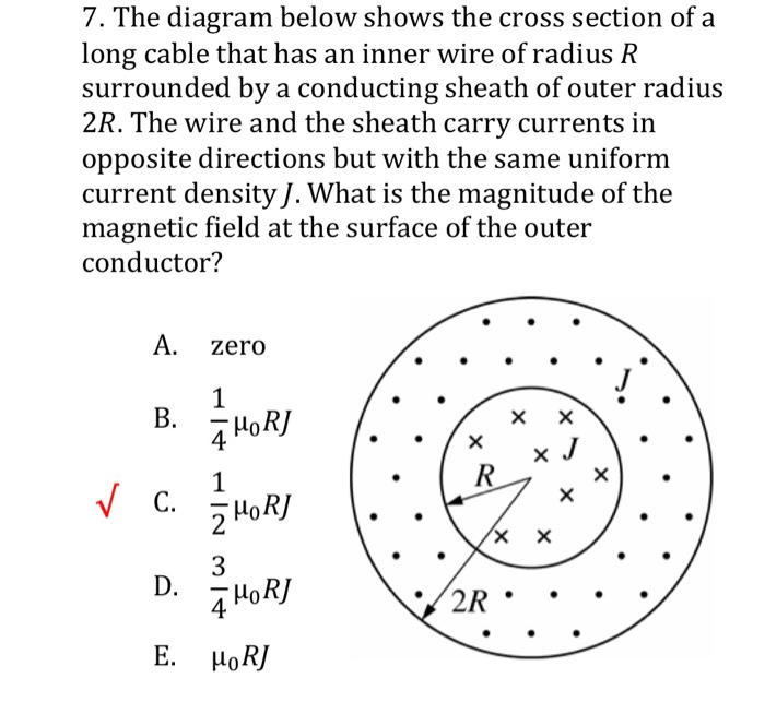
The solid circle of radius R in the diagram shows the cross section of a long wire that contains a current into the page with uniform current density Jo. The dashed concentric circles are four integration paths in a plane perpendicular to the length of the wire that have radii of rı = R/3, r2 = R/2, 13 =2R, and r4 = 4R.
The figure shows a wire that is connected to a power supply and suspended between the poles of a magnet. When the switch is closed, the wire deflects in the direction shown. The figure shows a circular cross section of a wire placed between four dashed boxes, labeled from A to D. The wire is located at the same distance from all the boxes.
The diagram shows the cross section of a wire carrying conventional positive current. The diagram shows the cross section of a wire carrying conventional postive current into the plante. The magnetic field exerts a force on the wire toward point 1 a 3 c 2 b 4 d 37. The wire is between the poles of a permanent magnet.
180 seconds. Report an issue. Q. Base your answer on the geologic cross section of a portion of Earth’s crust shown and on your knowledge of Earth science. None of the rock units has been overturned. The youngest rock unit shown in the cross section is. answer choices. breccia. conglomerate.
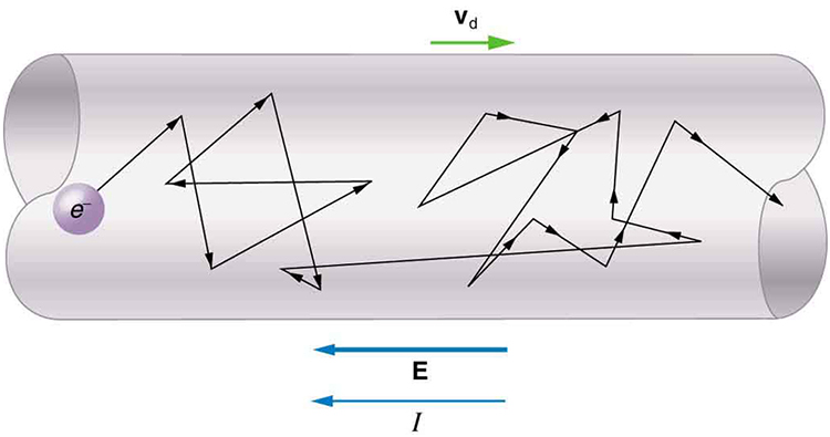
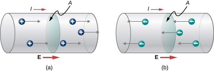
The Diagram Shows The Cross Section Of A Wire Carrying Conventional Positive Current Wiring Site Resource
The diagram shows two wires, P and Q, of equal length, joined in series with a cell. A voltmeter is connected between the end of Q and a point X on the wires. The p.d. across the cell is V. Wire Q has twice the area of cross-section and twice the resistivity of wire P. The variation of the voltmeter reading as the point X is moved along the ...
Each diagram shows a cross-section through two parallel conductors, each carrying an electric current. In the conductor on the left, the current is into the page; on the right, it is out of the page.

Modeling And Principles Of Ionic Polymer Metal Composite Electroactive Polymers As Actuators For Position Reconfigurable Devices Edicion Unica
Jun 17, 2016 · 4 Magnetic field lines show the shape and direction of a magnetic field. (a) The diagram shows a cross-section through a wire placed between two magnetic poles. The wire carries electric current into the page at X. The shape of the magnetic field is shown. (i) Add arrows to two of the magnetic field lines to show the direction of the magnetic ...

The Diagram Shows The Cross Section Of A Wire Carrying Conventional Positive Current Wiring Site Resource
1 Magnetic field lines show the shape and direction of a magnetic field. (a) The diagram shows a cross-section through a wire placed between two magnetic poles. The wire carries electric current into the page at X. The shape of the magnetic field is shown. (1) (i) Add arrows to two of the magnetic field lines to show the direction of the ...
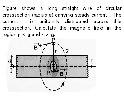
Figure Shows A Long Straight Wire Of Circular Crosssection Radius A Carrying Steady Current I The Current I Is Uniformly Distributed Across This Crosssection Calculate The Magnetic Field In The Region R
Q1.€€€€€€€€€ (a)€€€€ The diagram shows the cross-section of an eye. Use words from the box to label the parts, A, B and C. € (3) cornea€€€€€€€€€ iris€€€€€€€€€€ lens€€€€€€€€€ pupil€€€€€€€€€€€€ retina
magnitude 25N and acts at an angle of 15 to the horizontal, as shown in the diagram. Find (i) the work done by the pulling force in moving the crate a distance of 2m, [2] (ii) the normal component of the contact force on the crate. [3] 4 The diagram shows a vertical cross-section of a surface. A and B are two points on the cross-section.
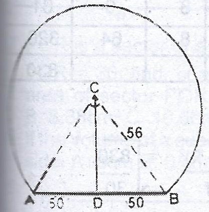
2007 Waec Mathematics Theory The Diagram Shows The Cross Section Of A Railway Tunnel If Ab 100m And Myschool
The diagram shows a conical section fabricated from pure aluminum. The end temperatures are t 1 600k and t 2 400k while the lateral surface is well insulated. The small end is located at and the large end at. Sketch the temperature distribution. It is of circular cross section having diameter d ax12 where a 05m12.
Apr 01, 2010 · Wire between two magnets. The diagram shows a straight wire carrying a flow of electrons out of the page. The wire is between the poles of the permanent magnet. The direction of the magnetic force exerted on the wire is: Please Note: My diagram isn't perfect but both magnets are the same size and the wire is equidistant from both of the magnets.
The Diagram Shows The Cross Section Of A Wire Carrying Conventional Positive Current Wiring Site Resource

Insulation Installation Yourhome Installing Insulation Reflective Insulation Reflective Foil Insulation
Metals Free Full Text Plasma Multiwire Technology With Alternating Wire Feed For Tailor Made Material Properties In Wire And Arc Additive Manufacturing Html

The Diagram Shows The Cross Section Of A Wire Carrying Conventional Positive Current Towards Us Out Of The Plane Of The Paper You May Ignore The Earth S Magnetic Field A By Means

Figure Shows Wire 1 In Cross Section The Wire Is Long And Straight Carries A Current Of 4 Ma Out Of The Page And Is At Distance D1 2 40 Cm
Solved 6 Pts A Coaxial Cable Has Central Cable Radius Rithat Carries Current Forward And An Outer Conducting Sheath Between Radii Rz And R3 That Carries Return Current The Diagram Shows A

Figure A Shows In Cross Section Three Current Carrying Wires That Are Long Straight And Parallel To One Another Wires 1 And 2 Are Fixed In Place On An X Axis With Separation






0 Response to "39 the diagram shows the cross section of a wire"
Post a Comment