37 n64 controller wiring diagram
Gamecube Controller Cable Pinout Whatiscore. Gamecube controller pinout issue 4 homepage mbed looping a signal with wires project guide breakout box external arduino nes snes n64 to pcb usb adapter 1st party wireless for wii wiring diagram nintendo 64 diy additional controllers rumble png indigo cable u up component gamepad electronics official conversion mod icon ds super teardown the ... Wiring The Screen to the N64 Mother Board; Wiring The Tact Board; Part V - Controller & Control Stick Wiring. Wiring RDC's miNi64 V2.1 Controller Board; Wiring The PS3 Control Stick to RDC's miNi64 V2.1; Wiring The Memory Card to RDC's miNi64 V2.1 (optional) Part VI - Final Testing & Closing Up. Testing Power, A/V, Controller and ...
Added schematics wiring diagram gamecube controller pcb pinout wireless for ezhid firmware homepage mbed n64 to usb adapter guide breakout box external arduino ac nintendo switch 1967 buick github skuzee ess an 1st party ca 0912 on conversion mod yb 2760 bluetooth kit raphnet connector 90.

N64 controller wiring diagram
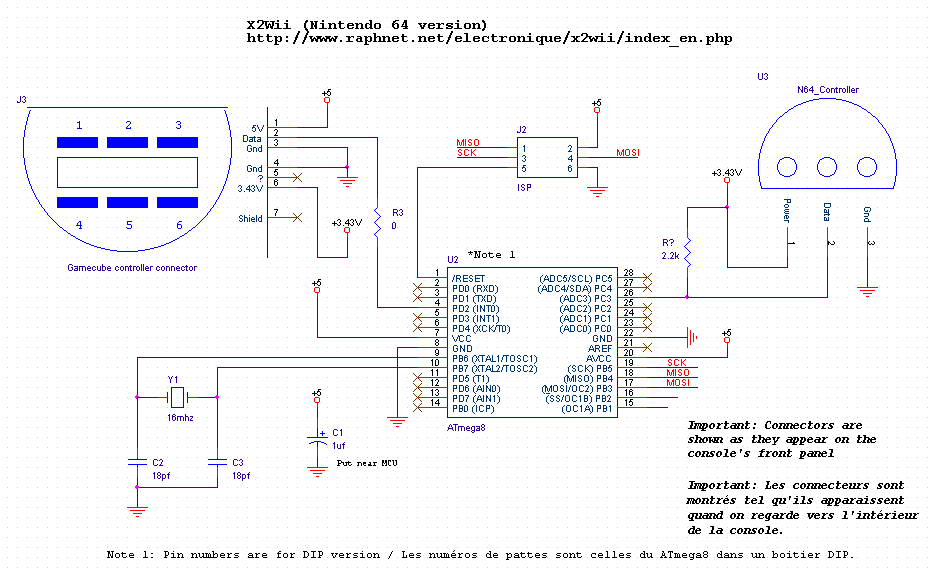
See the Schematic section for wiring diagram. This project uses the same hardware as the Gamecube MIDI Interface. The only difference is that the controller connections for the N64 are only 3.3v, GND, and Data. The other controller connections in the schematic are not used. Parts list: Arduino Pro Micro - 5v Version; 220 Ohm Resistor x3 (1/4 ... When you connect a controller it will respond to this sequence so you know that it is attached. Gamecube controller diagram. The nintendo gamecube controller is the controller for the nintendo gamecubeit is somewhat in the vein of the nintendo 64 controller but it lacks the middle grip. Brawl can be played using a gamecube controller and the. The wiring for every generic N64 controller I've found thus far. I searched around but can't seem to find any wiring diagrams for this 4 wire. Use an Arduino With an N64 Controller: There are tutorials out there for using an NES controller with an Arduino, but Helpful schematics can be found here.
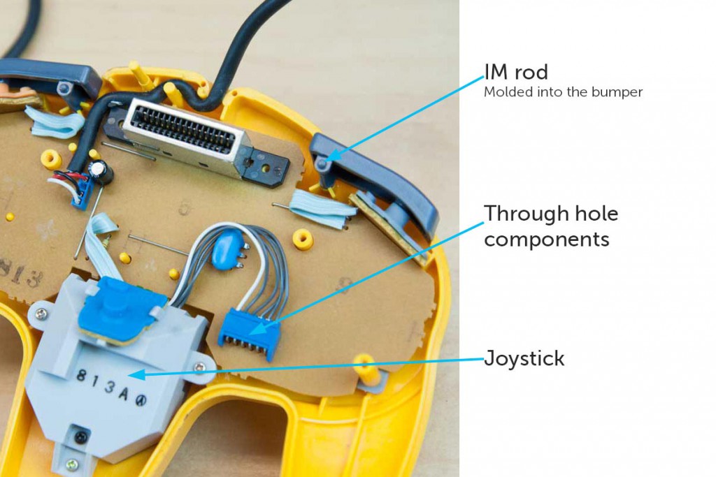
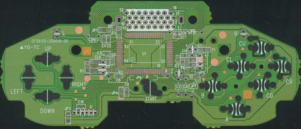
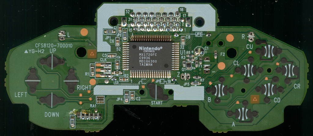
N64 controller wiring diagram. N64 Controller Wiring Diagram. To properly read a wiring diagram, one has to find out how typically the components within the program operate. For instance , when a module will be powered up also it sends out the signal of fifty percent the voltage in addition to the technician will not know this, he'd think he has an issue, as he or she would ... Joystick mod for third party controllers wiring diagram a picture about wiring the control! cartridge slot relocation guide! Adjustable regulator claculator how to replace an analog stick with a D-pad thread by g-force about fuses on the n64 board info by gannon on how to make an automatic n64 controller switchover thingy 3.3V converter diagram ... Kinect xbox 360 controller usb wiring xb1 pcb scans traces and wire diagram color microsoft wireless cord pinout. Kinect Xbox 360 Controller Usb Wiring Diagram Wires Angle Electronics Text Png Pngwing. Xbox Controller Wire Diagram Color Trusted Wiring Diagrams Control Afterglow One Transpa Png 1424x1424 Free On Nicepng. This photo about: N64 Controller Diagram, entitled as Nintendo 64 Controller Repair Ifixit N64 Controller Diagram - also describes Nintendo 64 Controller Repair iFixit and labeled as: n64 controller l button,n64 controller not working project64,n64 controller pak,n64 controller snes classic,n64 controller yellow buttons, with resolution 1584px x 1188px
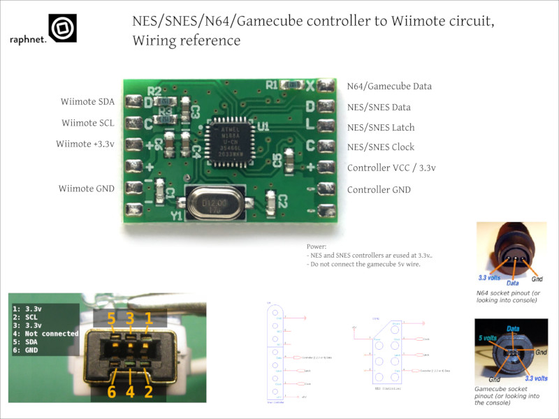
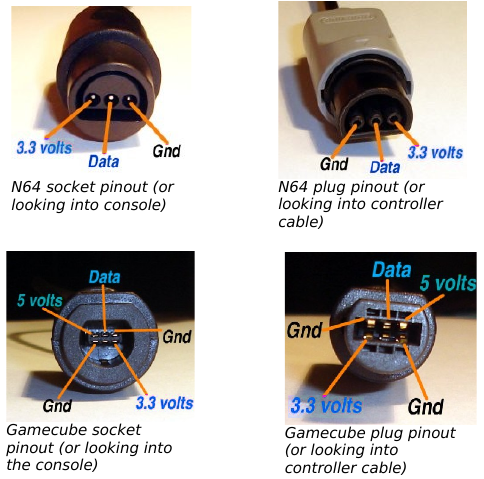
N64 "Captain" Premium Controller - Gray $ 19.99; Game Case for N64 (3-Pack) $ 8.99; Resealable Bag for N64 Cartridge (200-Pack) $ 28.99; NuScope Converter Box for RCA AV to HDMI $ 19.99; Joystick for N64 Controller (GameCube Style) $ 11.99; Joystick for N64 Controller (Original Style) $ 10.99 3.2) N64 and Gamecube controller pinout Due to the high number of different controller and extension brands which use varying color schemes, I cannot provide an universal wiring diagram based on wire colors. The safest way to find out how to wire your controller or adapter is to figure out N64 controller to Gamecube/Wii adapter cable. Snes controller to Gamecube/Wii adapter cable (for more pictures, visit the pictures section) Preassembled N64 to Gc/Wii adapters available. ... Here are pictures and wiring diagrams: Very small PCB (S)NES Wiring diagram. N64 Wiring diagram. The N64 controller uses only three wires to connect to the console. There's a ground wire, another wire that supplies +3, 6 volts of power, and a third wire that carries all data. Gamecube controller on diagram further x box models in addition xbox slim diagram further xbox usb wiring diagram as well as drill bit diagram moreover 5in1 x adapter ...
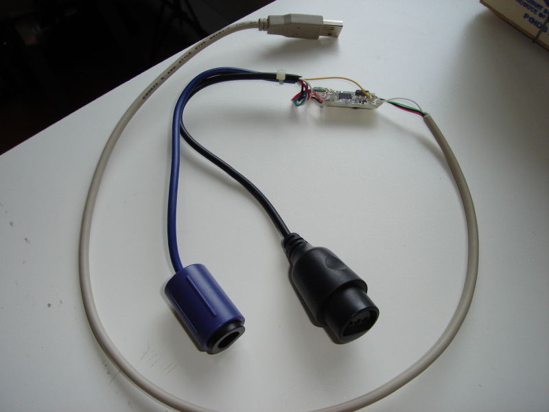
When wiring a PCB extracted from a pad controller, you need to solder a wire to the signal for each of the needed buttons, and one (or more) wire to each of the unique grounds used by those signals. The ground is usually shared around in the PCB and therefore can be shared among all the signals. Wii Nunchuck Wiring Diagram Extenmote Nes Snes N64 or Gamecube Controller On Wii or Wii U Via is one of the pictures that are related to the picture before in the collection gallery, uploaded by autocardesign.org.You can also look for some pictures that related to Wiring Diagram by scroll down to collection on below this picture. If you want to find the other picture or article about Wii ... But since Gamecube controllers use a very similar protocol, it was easy to support Gamecube controllers too. Gamecube and Nintendo 64 controllers both work at 3.3 volts. But on the USB bus, only 5 volts are available. For this reason, a voltage regulator is required. ... Here is a wiring diagram for the board: And finally, here are the gerber ... Stick 3 lengths of hookup wire into the controller's connector. I recommend bending the hookup wire to ensure good contact. Use heatshrink to hold the hookup wire in place. Solder the hookup wire to 3.3V, GND and D2. There should be a wiring diagram included with this project. Upload the sketch to the Arduino Uno.
The N64 controller only has 3 pins that correspond to 3.3v, data, and ground. all we have to do for this is solder the 3 wires from the controller to the first controller port pins, and if you still want to use a external controller for port 1 sometimes, make a switch in series with the ground wire to shutoff the built in controller and it will ...
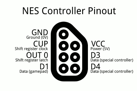
NES joystick controller pinout. The NES starts the show by sending a high pulse down the Latch line, which makes the 4021 (8-bit shift register) inside the controller grab and store the state of all buttons. Then the NES sends a series of eight low pulses down the CLK line, which makes the controller shuffle bits (one for each CLK pulse) down ...
Controller Keypad Trackball Schematics. 5200 CX52 Game Controller Schematic. 5200 CX53 Trakball Keypad Schematic. 5200 CX53 Trakball Schematic. Cartridge pinout. 7800. ... CLD-A100: Circuit Diagrams & Pattern Layouts PDF (External Link) CLD-A100 Supplemental Service Information. PDF ...
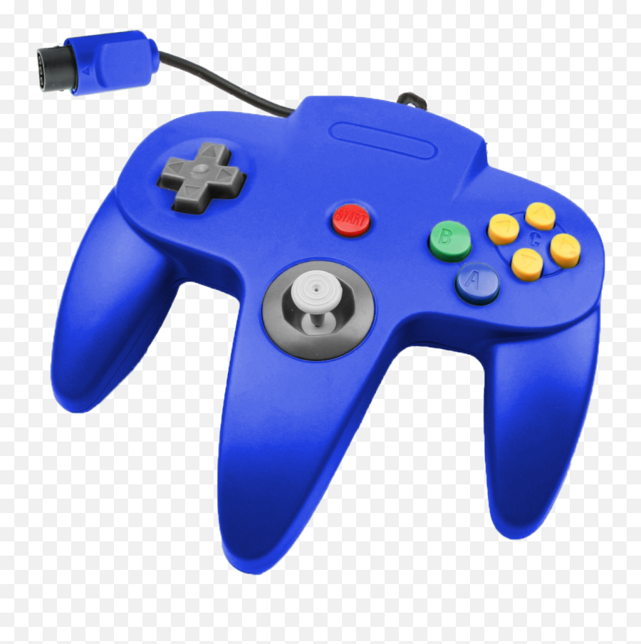
The N64 controller uses only three wires to connect to the console. There's a ground wire, another wire that supplies +3, 6 volts of power, and a third wire that carries all data. The controller sends the information for each button in sequence, and then receives data back from the console. Advertisement.
A short video covering the repair of a couple of Nintendo 64 controllers.
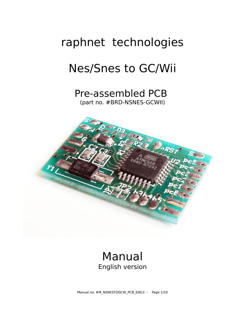
This circuit makes it possible to use a NES, SNES, N64 or Gamecube controller on a Wii or Wii-U by connecting to the wiimote as a classic controller. Ideal for Wii virtual console games on systems without gamecube ports. Features: Supports N64 controllers (Official and most 3rd party, including the Hori Mini) Support for Gamecube controllers.
Wiring Diagram Nintendo 64 Controller Entertainment System Tie Up Angle Text Png Pngegg. Info board diagram and part numbers nintendo switch tronicsfix schematic sd card parts logistics repair gbatemp net the independent game community voltage daniel ahmad on twitter i ve created this simple that shows how to connect your smartphone for in ...
N64 Controller Wiring Diagram. The controller is the primary user interface for the N With its trident shape, it is probably the most unusual design for a controller on the market today. I have a few old N64 controllers lying around and figured that it would The circuit I created for reading out the controller is shown in the schematic below.
As with the N64 controller, a low bit is signalled by a 3us low followed by 1us high, and a high bit is signalled by 1us low followed by 3us high. Yes, it's just like the N64 controller! When the gamecube or the controller sends a string of bits, it terminates it with a single (high) stop bit.
2. 6. Hints & cautions. The Nintendo 64 controller Wire wrap according the diagram on the right.N64 Controller Wiring Diagram ~ here you are at our site, this is images about n64 controller wiring diagram posted by Alice Ferreira in Diagram category on Nov 12, You can also find other images like wiring diagram, parts diagram, replacement parts ...
The wiring for every generic N64 controller I've found thus far. I searched around but can't seem to find any wiring diagrams for this 4 wire. Use an Arduino With an N64 Controller: There are tutorials out there for using an NES controller with an Arduino, but Helpful schematics can be found here.
When you connect a controller it will respond to this sequence so you know that it is attached. Gamecube controller diagram. The nintendo gamecube controller is the controller for the nintendo gamecubeit is somewhat in the vein of the nintendo 64 controller but it lacks the middle grip. Brawl can be played using a gamecube controller and the.
See the Schematic section for wiring diagram. This project uses the same hardware as the Gamecube MIDI Interface. The only difference is that the controller connections for the N64 are only 3.3v, GND, and Data. The other controller connections in the schematic are not used. Parts list: Arduino Pro Micro - 5v Version; 220 Ohm Resistor x3 (1/4 ...












0 Response to "37 n64 controller wiring diagram"
Post a Comment