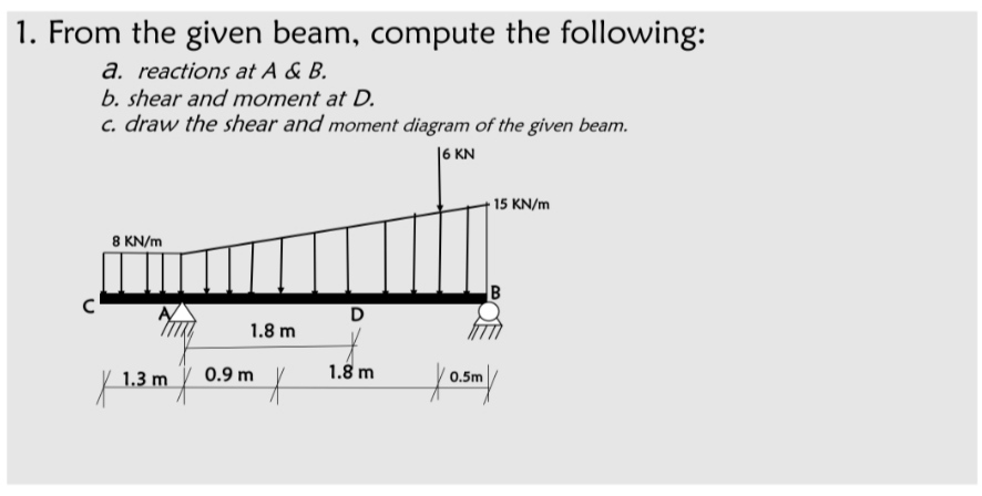
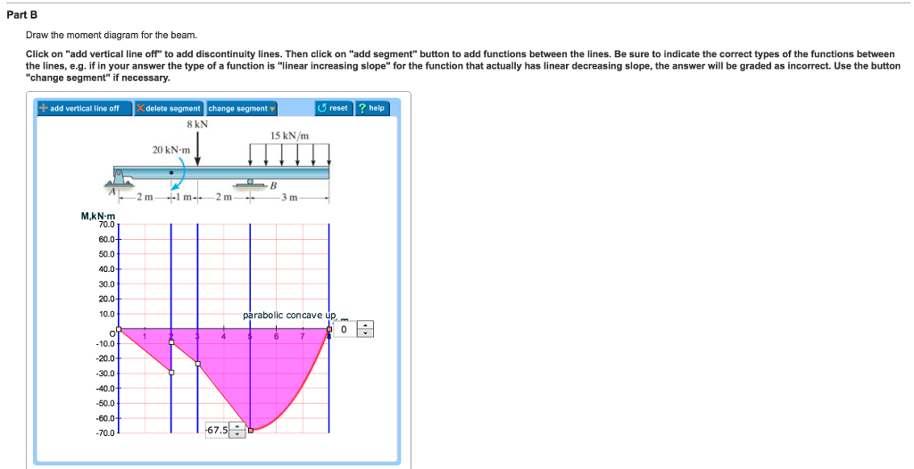
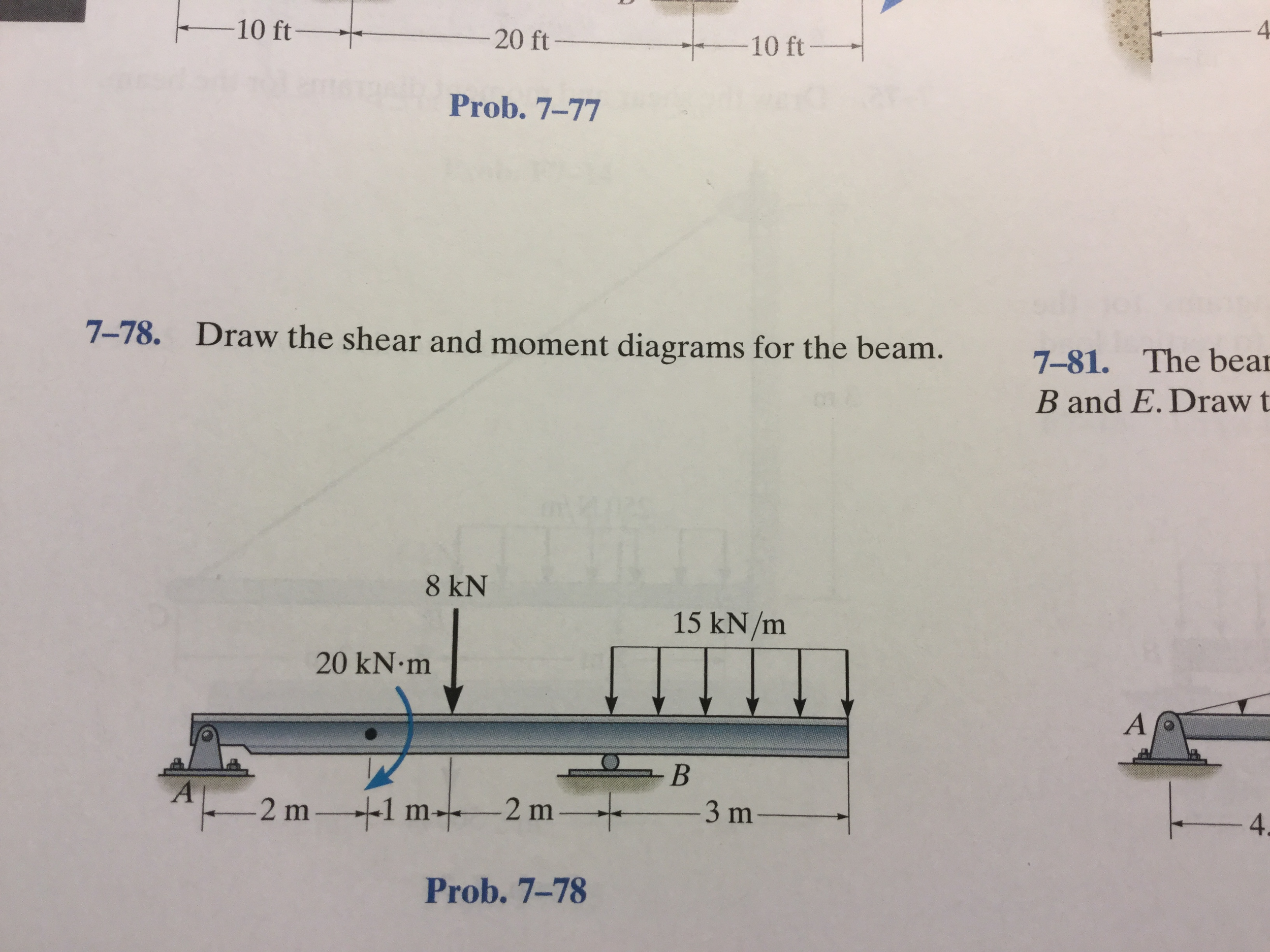
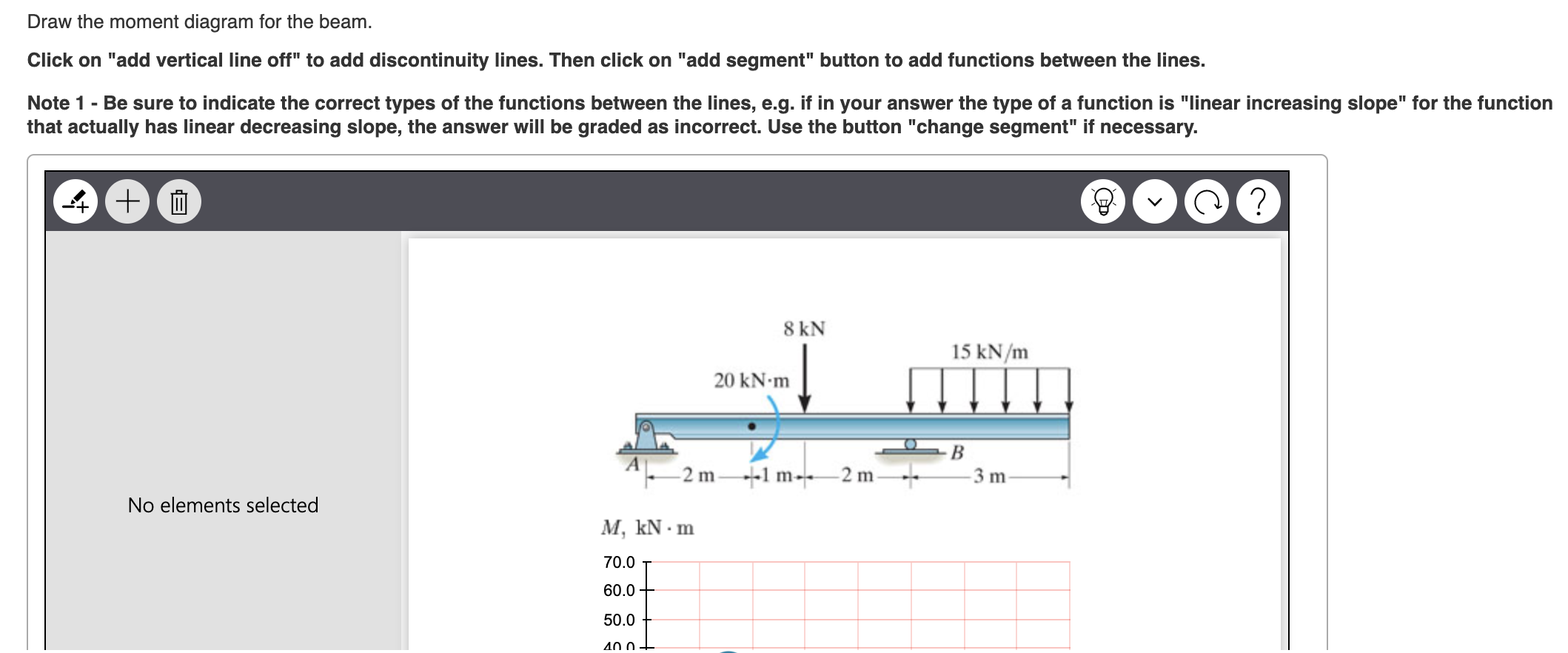
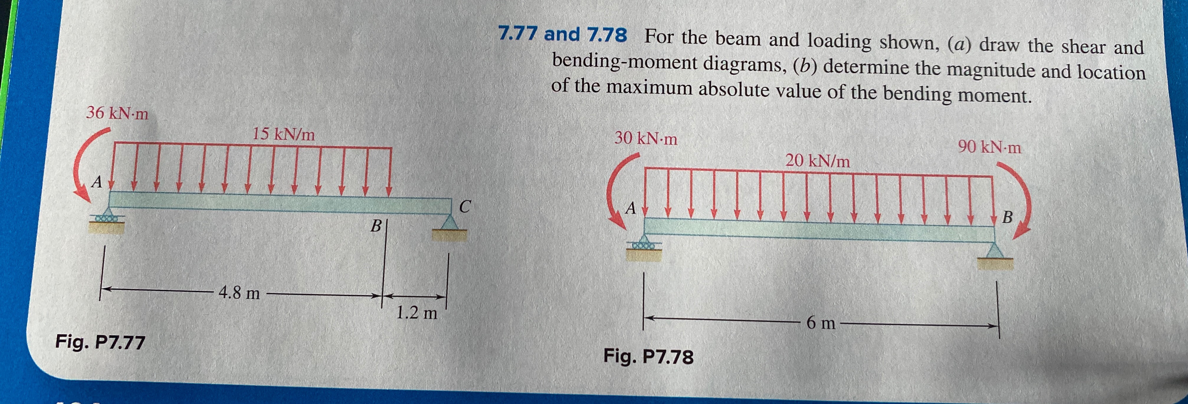
39 problem 7.78 part a draw the shear diagram for the beam.
Solution Manual - Mechanics Of Materials 7th Edition, Gere ... Solution Manual - Mechanics Of Materials 7th Edition, Gere, Goodno - ID:5c18dde35afdf. 00FM.qxd 9/29/08 8:49 PM Page i An Instructor’s Solutions Manual to Accompany ISBN-13: 978-0-495-24458-5 ISBN-10: 0-495-... Operation And Maintenance Manual For Electrostatic ... The five main types of precharges now being tested are: 1) The Air Pollution Systems high-intensity ionizer 2) The trielectrode precharger 3) The boxer charger 4} The ion beam charger 5) The cooled-pipe charger Work is continuing to improve the precharging mechanism and to deal with the problem of keeping a high electric field in the collector ...
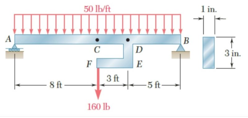
(Solved) - (a) Determine the magnitude and ... - Transtutors Solve Prob. 7.78 assuming that the 2-kip force applied at E is directed upward. Problem 7.78: For beam AB, (a) Draw the shear and bending-moment diagrams, (b) Determine the location and magnitude of the maximum absolute value of the bending moment.

Problem 7.78 part a draw the shear diagram for the beam.
CIVIL ENGINEERING | The civil engineering updates Draw shear force and bending moment diagram of simply supported beam carrying uniform distributed load and point loads. As shown in figure. Solution. First find reactions R1 and R2 of simply supported beam. Reactions will be equal. Since, beam is symmetrical. R1 = R2 = W/2 = (600 +600 + 200 x4)/2 = 1000kg. Hence, R1 = R2 = 1000 kg. Shear Force ... Shear force and bending moment diagram practice problem #2 ... Check out for more free structural analysis tutorials. The course covers shear force and bending moment diag... Solved Problem 7.77 Part A Draw the shear diagram for the ... Then click on "add segment" button to add functions between the lines Note 1- You should not draw an "extra" discontinuity line at the point where the curve passes the x-axis Note 2 Be sure to indicate Question: Problem 7.77 Part A Draw the shear diagram for the beam. Follow the sign convention.
Problem 7.78 part a draw the shear diagram for the beam.. PDF WordPress.com WordPress.com Solution x a Σ F y 0 V w x V w x Σ M 0 M w ... - Course Hero Solution x a Σ F y 0 V w x V w x Σ M 0 M w x x 2 M w x 2 2 a x 2a Σ F y 0 V 2 w from MT 423 at National Taiwan University 7 53 Draw The Shear Diagram For Cantilevered Beam - The ... 7 53 Draw The Shear Diagram For Cantilevered Beam. Ering mechanics statics pages 351 solved for all the problems draw solved for all the problems draw bending moment diagram an overview problem 7 53 part a draw the shear. 329 6 1 Draw The Shear And Moment Diagrams For Shaft Bearings At A B Exert Only Vertical Reactions On. Drawing Shear and Moment Diagrams Example ... - YouTube this is a detailed example of shear and moment diagrams, i recommend skipping around to the sections shown below if you already have a feel for the subject:i...
Answered: 7.77 and 7.78 For the beam and loading… | bartleby 7.77 and 7.78 For the beam and loading shown, (a) draw the shear and bending-moment diagrams, (b) determine the magnitude and location of the maximum absolute value of the bending moment. Question thumb_up 100% Plz solve for 7.77 Thx Probability & Statistics for Engineers & ... Shrinkage is often a major problem. Thus, a molded die for a part is built larger than nominal size to allow for part shrinkage. In an injection molding study it is known that the shrinkage is influenced by many factors, among which are the injection velocity in ft/sec and mold temperature in C. Cobb Fiona Structural Engineers Pocket Book ... - Academia.edu Academia.edu is a platform for academics to share research papers. Solved problem 7.78 Part A Draw the shear diagram for the ... Question: problem 7.78 Part A Draw the shear diagram for the beam. Click on "add vertical line off" to add discontinuity lines. Then click on "add segment" button to add functions between the lines. Note 1 - You should not draw an "extra" vertical line at the location of applied moment.
Solved 7-78. Draw the shear and moment diagrams for the ... This problem has been solved! 7-78. Draw the shear and moment diagrams for the beam. I attached the Prob. 7-78 as a picture shown. Who are the experts? Experts are tested by Chegg as specialists in their subject area. We review their content and use your feedback to keep the quality high. Draw the shear and moment diagrams for the beam. Prob. F7 ... Section: 7.3 Relations Between Distributed Load, Shear, And Moment. Problem 13FP: Draw the shear and moment diagrams for the beam. Prob. F7-13 Problem 14FP Problem 15FP Problem 16FP Problem 17FP Problem 18FP Problem 70P Problem 71P Problem 72P Problem 73P Problem 74P Problem 75P Problem 76P Problem 77P Problem 78P: Draw the shear and moment ... Mechanics of Materials 1260113272, 9781260113273 - … MODELING: Draw the free-body diagram of the bar (Fig. 1) and the bolts at B and C (Figs. 2 and 3). Determine the allowable value of the force C based on the required design criteria for each part. A C B D C B D 6 in. The rigid beam BCD is attached by bolts to a control rod at B, to a hydraulic cylinder at C, and to a fixed support at D. Problem Set 7 (Key) II - VSIP.INFO PROBLEM 7.78 For beam AB, (a) draw the shear and bending-moment diagrams, (b) determine the magnitude and location of the maximum absolute value of the bending moment. SOLUTION (a) Replacing the load at E with equivalent force-couple at C:
Vector Mechanics for Engineers Chapter 07.pdf - Academia.edu PROBLEM 7.17 A 5-in.-diameter pipe is supported every 9 ft by a small frame consisting of two members as shown. Knowing that the combined weight of the pipe and its contents is 10 lb/ft and neglecting the effect of friction, determine the magnitude and location of the maximum bending moment in member AC.
Fluid Mechanics Frank White 5th Ed - ID:5c142a11d322e Fluid Mechanics Frank White 5th Ed - ID:5c142a11d322e. Fluid Mechanics McGraw-Hill Series in Mechanical Engineering CONSULTING EDITORS Jack P. Holman, Southern Methodist Univ...
Ipho Problems And Solutions (1967-2010) [x256p78dvnop] Problem 2 Consider a parallel, transparent plate of thickness d – Fig. 1. Its refraction index varies as n= n0 x 1− R. y α B d A xB x Fig. 1 A light beam enters from the air perpendicularly to the plate at the point A (xA = 0) and emerges from it at the point B at an angle α . 1. Find the refraction index nB at the point B. 2.
[Solved] Design of unrestrained steel beam (EC3) The beam ... b. Shear Diagram: c. Moment Diagram: d. Design Moment and Shear: From the diagrams above: M Ed = 227.576 kN-m. V Ed = 74.60 kN (@ support) V c.Ed = 13.40 kN(0.489/1.488m) = 4.40 kN (@ midspan) Select trial beam size from Blue Book of Steel Construction: Initially select UB section in terms of bending resistance)
Mastering Engineering, Assignment--12--Beams ... - Course Hero Correct Problem 7.53 Part A Draw the shear diagram for the beam. Click on "add discontinuity" to add discontinuity lines. Then click on "add segment" button to add functions between the lines. ANSWER:
PDF ME 270 Final Exam - PM F20 (P2-P3 Soln) The beam is loaded as shown, and is in equilibrium. One concentrated load is applied at point C (+ 500N), a constant distributed load is applied between points A and B (+ 500N/m), and an external moment is applied at point D (+ 500 N-m). FIND: a) On the artwork provided below draw the free body diagram for the beam: (pts 3) ] $"""""!" = At → =-).
Draw The Shear Diagram For The Beam 778 - Kelse Web Draw the shear and moment diagrams for the beam (a) in terms of the parameters shown; Problem 7.78 part a draw the shear diagram for the beam. ∑ = ⇒ = − ⇒ = kn d d m y y c 25 0) 4) (50 8) ( (0 ∑ Correct problem 753 part a draw the shear diagram for the beam. 15+ Draw The Shear Diagram For The Beam 778 Pictures
Answered: 8 kN 15 kN/m 20 kN-m A-2 m-f1 m--2 m ... - bartleby Solution for 8 kN 15 kN/m 20 kN-m A-2 m-f1 m--2 m- 3 m- Prob. 7-78. Q: Draw the shear and moment diagrams for the beam(a) in terms of the parameters shown; (b) set P = 800... A: Shear force and bending moment diagram are the variation of respective parameter along the length of...
Engineering Mechanics Statics (13th Edition) - R. C ... Homework Problems. Apart from the Fundamental and Conceptual type problems mentioned previously, other types of problems contained in the book include the following: • Free-Body Diagram Problems. Some sections of the book contain introductory problems that only require drawing the free-body diagram for the specific problems within a problem set.
Draw The Shear And Moment Diagrams For Beam 7 53 - New ... Problem 7 53 part a draw the shear chapter 7 78 draw the shear and moment diagrams chapter 7 solved draw the shear and moment ... Chapter 7 solved problem 7 53 part a draw the shear diagram for beam on 1 transtutors ering mechanics statics pages 351 400 flip fliphtml5 7 81 the beam consists of three segments pin connected at b and e draw shear ...
Solved 7.78 Draw the shear and moment diagram for the beam ... 7.78 Draw the shear and moment diagram for the beam. Question: 7.78 Draw the shear and moment diagram for the beam. This problem has been solved! See the answer See the answer See the answer done loading. 7.78 Draw the shear and moment diagram for the beam. Videos. Step-by-step answer.
(Solved) - Solve Prob. 7.78 assuming that the 2-kip force ... Solve Prob. 7.78 assuming that the 2-kip force applied at E is directed upward. Problem 7.78: For beam AB, (a) Draw the shear and bending-moment diagrams, (b) Determine the location and magnitude of the maximum absolute value of the bending moment. 1 Approved Answer deepak k answered on November 17, 2020 5 Ratings, ( 7 Votes) solution .pdf
7-55. Draw The Shear And Moment Diagrams For The Beam ... 778 draw the shear and moment diagram for the beam. Draw the shear and moment diagrams for the beam. Click on add vertical line off to add discontinuity lines. Answer to problem 780 part a draw the shear diagram for the beam. Then click on add segment button to add functions between the lines. 7 78 as a picture shown. More › More Courses ››
(Solved) - Problem 7.55 Part A Draw the shear diagram for ... Problem 7.78 Part A Draw the shear diagram for the beam. Click on "add vertical line off" to add discontinuity lines. Then click on "add segment" button to add functions between the lines. Be sure to indicate the correct types of the functions...
Solved Problem 7.78 Part A Draw the shear diagram for the ... This problem has been solved! See the answer Problem 7.78 Part A Draw the shear diagram for the beam. Click on "add vertical line off" to add discontinuity lines. Then click on "add segment" button to add functions between the lines.
[Solved] Solve Problem 6.157 assuming that the 2-kip force ... Solve Prob. 7.78 assuming that the 2-kip force applied at E is Solve Prob. 7.78 assuming that the 2-kip force applied at E is directed upward. Problem 7.78: For beam AB,(a) Draw the shear and bending-moment diagrams,(b) Determine the location and magnitude of the maximum absolute value of the bending...
Draw The Shear Diagram For Beam 7 55 - The Best Picture Of ... Solved 7 55 Draw The Shear And Moment Diagrams For Beam Chegg. Can Someone Solve A B For Me Please I Need An Accurate Draw Hw8 Shear And Moment Dlagrams Problem 7 55 Dr Homeworklib. Chapter 7. 329 6 1 Draw The Shear And Moment Diagrams For Shaft Bearings At A B Exert Only Vertical Reactions On.
University Physics with Modern Physics - SILO.PUB Part 2: Extended Objects, Matter, and Circular Motion 8 Systems of Particles and Extended Objects 246 9 Circular Motion 279 10 Rotation 312 11 Static Equilibrium 354 12 Gravitation 381 13 Solids and Fluids 417 Part 3: Oscillations and Waves …
(PDF) PROBLEM 6.1 | L Jose Rangel - Academia.edu PROBLEM 6.1. L Jose Rangel. Download Download PDF. Full PDF Package Download Full PDF Package. This Paper. A short summary of this paper. 1 Full PDF related to this paper. Read Paper. Download Download PDF.
(PDF) INTRODUCTION TO PHYSICAL METALLURGY - … Academia.edu is a platform for academics to share research papers.
(PDF) 7 Solutions 44918 | Adriano Cruz - Academia.edu No portion of this material may be reproduced, in any form or by any means, without permission in writing from the publisher. 7-78. The beam consists of two segments pin connected at 700 lb B. Draw the shear and moment diagrams for the beam.
Solved Problem 7.77 Part A Draw the shear diagram for the ... Then click on "add segment" button to add functions between the lines Note 1- You should not draw an "extra" discontinuity line at the point where the curve passes the x-axis Note 2 Be sure to indicate Question: Problem 7.77 Part A Draw the shear diagram for the beam. Follow the sign convention.
Shear force and bending moment diagram practice problem #2 ... Check out for more free structural analysis tutorials. The course covers shear force and bending moment diag...
CIVIL ENGINEERING | The civil engineering updates Draw shear force and bending moment diagram of simply supported beam carrying uniform distributed load and point loads. As shown in figure. Solution. First find reactions R1 and R2 of simply supported beam. Reactions will be equal. Since, beam is symmetrical. R1 = R2 = W/2 = (600 +600 + 200 x4)/2 = 1000kg. Hence, R1 = R2 = 1000 kg. Shear Force ...












0 Response to "39 problem 7.78 part a draw the shear diagram for the beam."
Post a Comment