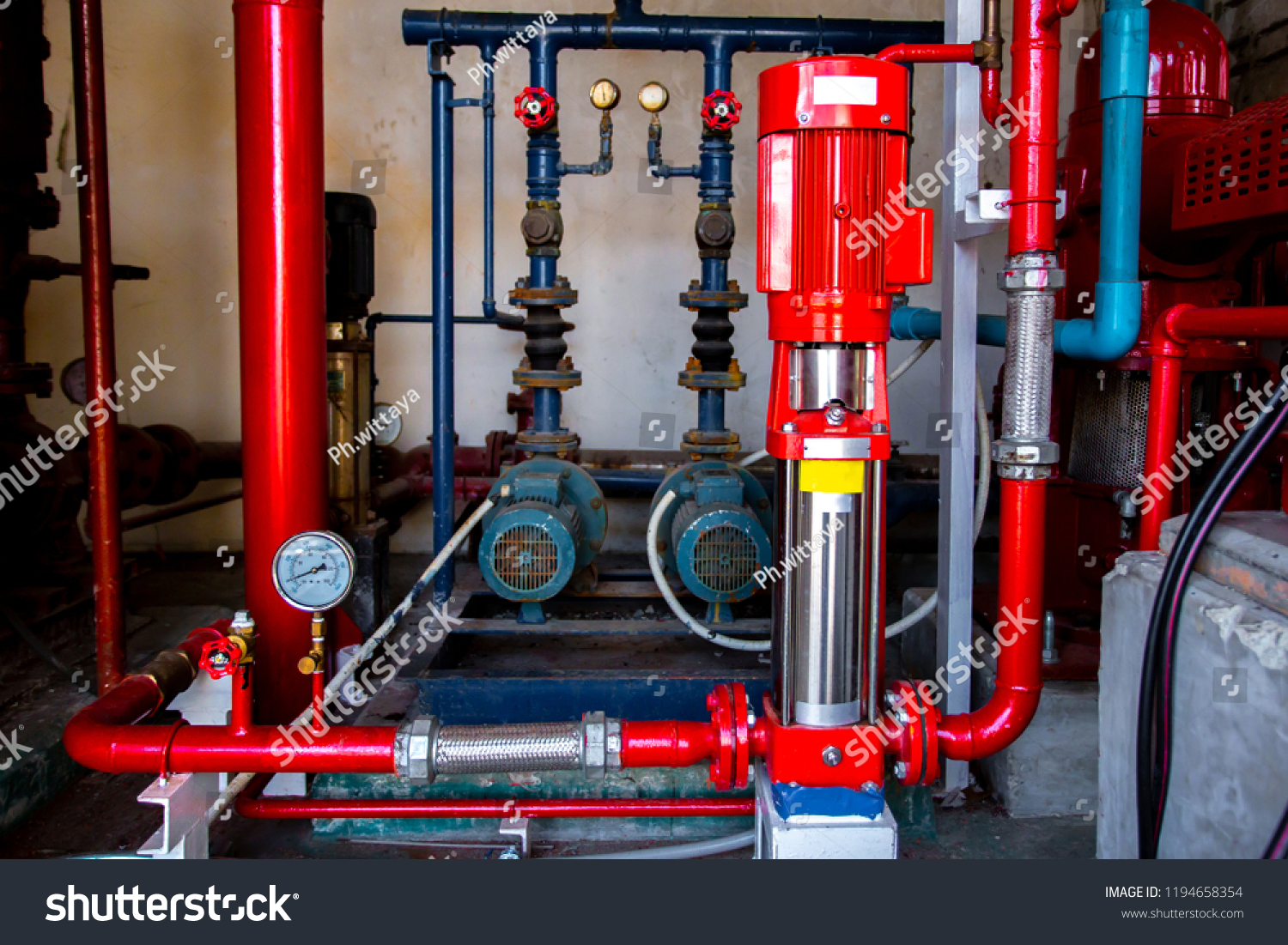
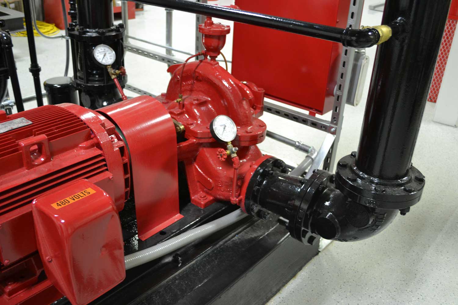
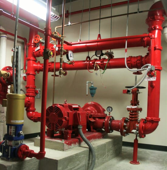
39 jockey pump piping diagram
Typical Configuration of Pump in Piping and ... Figure above reprsents typical piping and instrumentation diagram of pump. Pump should have: Pump Symbol. Make sure you use proper pump symbol. As for example above, I use centrifugal pump. Check your P&ID legend All the nozzles should be correctly represented with size and flanges. Installing Sensing Lines in Jockey and Fire Pump Systems Mar 12, 2019 · The first part is understanding that the jockey pump and the fire pump need to be located on the high-pressure side of the fire pump piping. Generally, the layout will be the pump suction or inlet, the pump discharge or outlet, and then you must pipe onto the fire pump discharge piping a ¾ “casing relief valve.
The Jockey Pump, an Important Part of a Fire Pump System. The Jockey Pump, an Important Part of a Fire Pump System. August 1, 2009 Rev. No. 2 A Jockey Pump is an important component of a fire pump system. The Jockey Pump is not as mundane as many engineers, contractors, and installers would have you believe. Why are they so misunderstood? The Jockey Pump (JP) or Pressure Maintenance Pumps (PMP) as ...
Jockey pump piping diagram
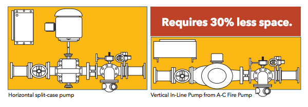
NFPA 20: Fire pump design - Consulting-Specifying Engineer H orizontal split case pumps are only permitted to have elbows and tees installed perpendicular to the pump when the fitting is located at least 10 pipe s ize diameters from the suction flange (NFPA 20-2013, Section s 4.14.6.3.1 to 4.14.6.3.3). Piping diagrams - Raypak Raypak Pool & Spa, Residential and Commercial Hydronic Products - This Piping Diagram Is Raypak'S Recommendation and Is Not ... THIS PIPING DIAGRAM IS RAYPAK'S RECOMMENDATION AND IS NOT INTENDED TO REPLACE AN ENGINEERED PIPING SYSTEM DESIGNED BY A PROFESSIONAL ENGINEER. COLD ~- WATER "-. ~ HEA.TER-MOUNTED PRESSURE RELIEF VALVt_ 6 1. PLUMl3 SWING CHECK VALVE IN CRAVITY-CLOSED POSITION. 6 PIPE ~LL RC:L~EF '/." L VES TO C'?A.!N, C'R AS ' OCAL. CODES REQII!RE.
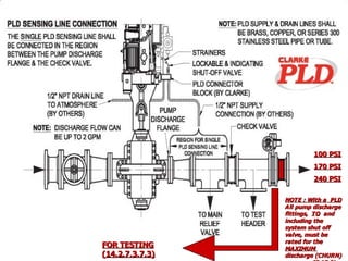
Jockey pump piping diagram. Fire and Jockey Pump Controller Sensing Lines The above capture is an age-old drawing covering sensing lines for a jockey pump and fire pump controller. Each controller is required to have its own individual sensing line like below. This... Fire Pump Installation Inspection Checklist.pdf Fire pump and controller, piping, gauges, jockey pump, and other component locations and design are the same as shown on the approved set of plans. 8. Fire pump has name plate. 9. Wire installation to motor, control inner wiring, and jockey pump wiring is correct. 10. A pressure gauge not less than 3 ½ in. diameter is near the pump discharge ... Fire Pump Room AutoCAD Drawings, dwg Layouts for Pump Room Download Fire Pump Room AutoCAD Layouts. Pump rooms containing fire pump equipment require special design as outlined in NFPA 20. Pump rooms may be implemented in various design but all should be under the constrains of NFPA 20. We provides you with several fire pump room AutoCAD drawings, take them as a reference for your future design. PDF QUICK RESPONSE Fire Pumps - Sensing Lines.doc - pdfMachine ... D = Jockey Pump Controller C D A B January 2009 From Supply To System F E FIRE PUMPS Œ SENSING LINES Most commonly the pump controller is connected to the fire protection system by means of piping know as a sensing or pilot line. Each pump, including the jockey pump, shall have its own individual
PDF Instruction Bulletin - Fire Pump Sales & Services Piping 5 Setting the Pressure Switch 6 ... The controller is intended to be mounted to a wall or a welded structure that is part of the pump package. Refer to the Outline Diagram for mounting hole sizes and locations. If the controller is ... The jockey pump controller has a Hand-Off-Auto selector switch on the right hand side of the Jockey Pump Requirements & Sizing - NFPA 20 - Fire Protection ... Oct 13, 2018 · A fire pump with rated capacity of 1500 gpm. Then the jockey pump flow rate is 1500 gpm * 1% = 15 gpm. Jockey Pump Head: Pressure of jockey pump shall be greater than the pressure of main fire pump by minimum of 10 psi to avoid false starting of main fire pump. For more information about setting of fire pumps, click here. PJPC Jockey Pump Controller - Peerless Pump Figure A-10-5.2.1(a) Piping connection for each automatic pressure switch (for fire pump and jockey pumps). If water is clean, ground-face unions with non-corrosive diaphragms drilled for 3/32-in. orifices can be used in CoNLL17 Skipgram Terms | PDF | Foods | Beverages - Scribd CoNLL17 Skipgram Terms - Free ebook download as Text File (.txt), PDF File (.pdf) or read book online for free.
Fire Water Pump Station Design, Piping ... - Cad Crowd Fire Water Pump Station Design, Piping Instrumentation Diagram (P&ID), Flow diagrams and Hydraulic Calculations 2,997 views 28 comments (0 reviews) Sesinando Tibule PDF QUICK RESPONSE Fire Pumps - Jockey Pump.doc - pdfMachine ... A jockey pump, also know as a pressure maintenance pump, maintains the pressure in the fire sprinkler system to avoid non-emergency starting of the main fire pump. This keeps the main fire pump from short cycling, which shortens its life span. The jockey pump is designed to start before Jockey pump in fire system - Grundfos Research And Insight Jockey pump A jockey pump is a small pump connected to a fire sprinkler system to maintain pressure in the sprinkler pipes. This is to ensure that if a fire-sprinkler is activated, there will be a pressure drop, which will be sensed by the fire pumps automatic controller, which will cause the fire pump to start. Piping arrangements for fire pumps - Specifying Engineer Mar 16, 2015 · The jockey pump pressure switch is normally set at a higher pressure so that the jockey pump starts before the fire pump. Note that each controller, the one for the jockey pump and the one for the fire pump, must have its own independent pressure sensing line that connects the fire protection system with the pressure switches in each controller.
PDF Multistage Diffuser Pumps Types TMUB, TMUAH and J Jockey Pumps Multistage Diffuser Pumps Types TMUB, TMUAH and J Jockey Pumps Instructions • Installation • Operation • Maintenance ... that 2" or 2 ½" pipe be used for suction piping to reduce friction loss. It must be tight to prevent air leaks and ... the wiring as indicated on the motor wiring diagram.
General Information Fire Pump Controllers & Jockey Pump ... facilitate isolation of the jockey pump controller (and sensing line) for maintenance without having to drain the entire system. [See Figures A-7-5.2.1 (a) and (b).] A-7.5.2.1(e) The pressure recorder should be able to record a pressure at least 150 percent of the pump discharge pressure under no-flow conditions.
Jockey Pump Piping Diagram Jockey Pump Piping Diagram A jockey pump is a small pump connected to a fire sprinkler system and is intended to maintain pressure in a fire protection piping. Questions about the orifice checks in the SENSING LINES has come up quiet often. The above capture is an age-old drawing covering sensing lines for a jockey pump and fire pump controller.
PDF Instruction, Installation, Maintenance and Repair Manual ... any mechanical difficulties with the pump or motor. The 384 pump was properly aligned, if supplied with a motor, at the factory. However, since the pump base is flexible, it may spring and twist during shipment. Do not pipe the pump until it is realigned. Realign the base after piping is completed and after the pump is grouted in and bolted down.
PDF MASTER PIPING CONNECTIONS - A 1/4 inch nominal pressure sense line, typically made of brass, rigid copper or 300 series stainless steel, shall be connected to the incoming bulkhead connector located on the controller. The pressure sense line shall have two 3/32" orifices installed between the fire protection system and the bulkhead fitting.
PDF User's Manual - Pump Manufacturing Lag pump stops after the lag stop pressure is achieved and the flow rate is lower than the flow start setting for the off-delay time period. When all lag pumps are stopped, the jockey pump will restart and if the pressure is still being maintained, the pump will shut down after the off -time delay.
PDF Fire Pump Package Pumping Systems - Xylem Inc. Line up the vertical and horizontal piping so that the bolt holes of the flanges match. DO NOT ATTEMPT TO SPRING THE SUCTION OR DISCHARGE LINES INTO POSITION. Refer to assembly drawing for cus- tomer piping connections. 2.3.2 As a rule, ordinary wire or band hangers are not adequate to maintain alignment.
PDF INSTALLATION AND OPERATION INSTRUCTIONS Jockey Pump ... Firetrol FTA560 Jockey Pump Controllers are intended for use with fire pump systems. They ... piping procedure of the sensing line between the pumping system and the controller. ... consult the appropriate field connection diagram included with the manual. For proper wire sizing, refer to the National Electrical Code, NFPA 70.
PDF Patterson Pump Company Refer to NFPA 20 (or Publication GF 100-30) for correct field piping procedure of the sensing line between the pumping system and the controller. VOLTAGE CHECK 1. Energize the incoming power feeder. 2. Measure the line voltage at L1, L2 and L3 at the top of the disconnect switch.
Books on Google Play Private investigator and World War II veteran Aloysius Archer heads to Los Angeles, the city where dreams are made and shattered, and is ensnared in a lethal case in this latest thriller in #1 New York Times bestselling author David Baldacci’s Nero Award-winning series. It’s the eve of 1953, and Aloysius Archer is in Los Angeles to ring in the New Year with an old friend, aspiring …
PDF General Information Typical Pressure Sensing Line ... Figure A.10.5.2.1(a) Piping Connection for Each Automatic Pressure Switch (for Electric Fire Pump and Jockey Pumps). See Note See Note Minimum 5 ft. (1.5 m) Minimum 5 ft. (1.5 m) Figure A.10.5.2.1(b) Piping Connection for Pressure-Sensing Line (Electric Fire Pumps). Note: Check valves or ground-face unions complying with 10.5.2.1.
Fire Pump Controller Drawings - Master Control S JPCV and PMCVE Drawings. Dimensionals. 10605 - JPCV: NEMA 2, Variable Speed Jockey Pump Controller. 24180 - PMCVE: NEMA 2,12 Variable Speed Pressure Mainenance Controller. External Wiring. 10604 - JPCV: Three Phase Variable Speed Jockey Pump Controller.
This Piping Diagram Is Raypak'S Recommendation and Is Not ... THIS PIPING DIAGRAM IS RAYPAK'S RECOMMENDATION AND IS NOT INTENDED TO REPLACE AN ENGINEERED PIPING SYSTEM DESIGNED BY A PROFESSIONAL ENGINEER. COLD ~- WATER "-. ~ HEA.TER-MOUNTED PRESSURE RELIEF VALVt_ 6 1. PLUMl3 SWING CHECK VALVE IN CRAVITY-CLOSED POSITION. 6 PIPE ~LL RC:L~EF '/." L VES TO C'?A.!N, C'R AS ' OCAL. CODES REQII!RE.
Piping diagrams - Raypak Raypak Pool & Spa, Residential and Commercial Hydronic Products -
NFPA 20: Fire pump design - Consulting-Specifying Engineer H orizontal split case pumps are only permitted to have elbows and tees installed perpendicular to the pump when the fitting is located at least 10 pipe s ize diameters from the suction flange (NFPA 20-2013, Section s 4.14.6.3.1 to 4.14.6.3.3).










0 Response to "39 jockey pump piping diagram"
Post a Comment