41 pod brake controller wiring diagram
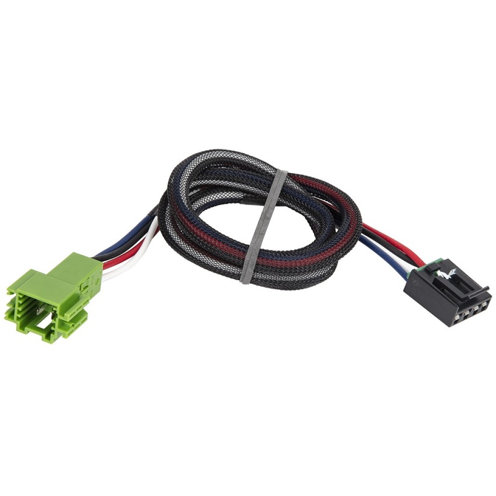
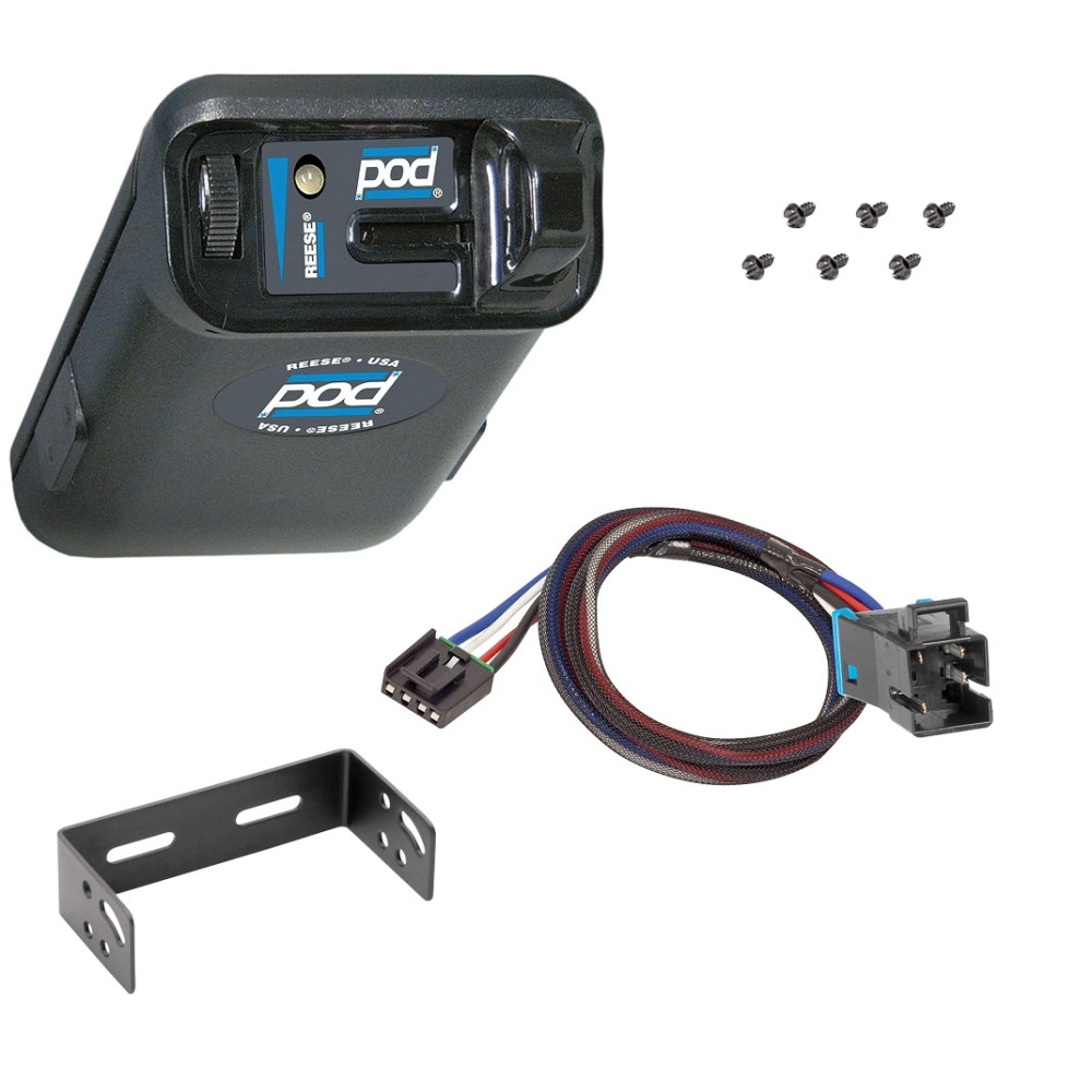
Reese Pod Brake Controller Wiring Diagram 1. Connect the supplied pigtail wiring harness into the electrical connection port on the rear of the pod brake controller. Purchase a wiring harness specific to your vehicle application from your vehicle's manufacturer, and plug that harness into the recommended connection portal. Reese has always strived to provide the right trailer towing ... Reese Pod Brake Controller Wiring Diagram - schematron.org Aug 16, 2018 · Reese Pod Brake Controller Wiring Diagram 16.08.2018 16.08.2018 6 Comments on Reese Pod Brake Controller Wiring Diagram schematron.org Today on this Chevrolet Silverado were going to install part number The Pod (Power on Demand) trailer brake control is your best choice, Accu- Power Pod Brake Controller, Tekonsha Installation Instructions ...
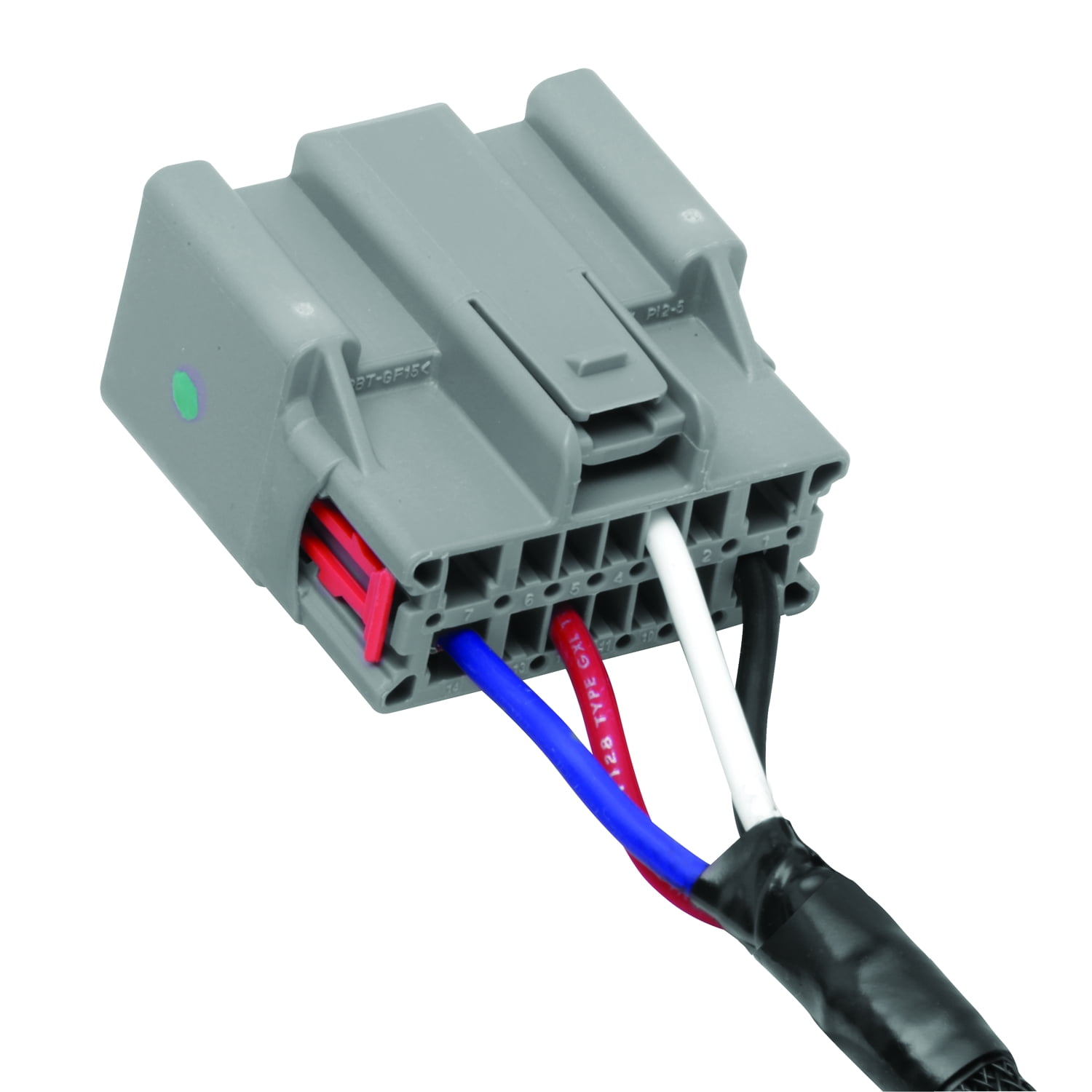
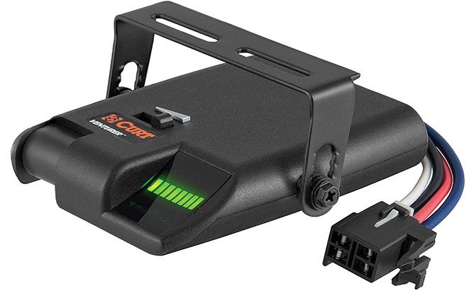
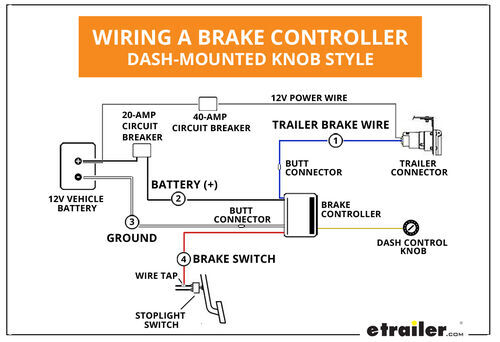
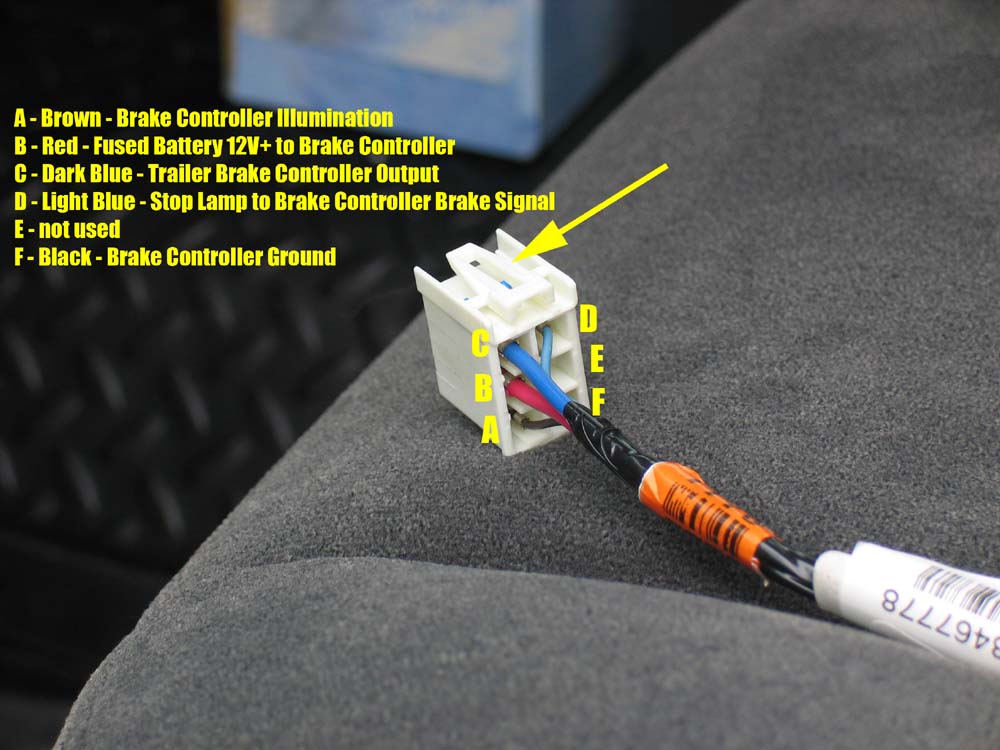
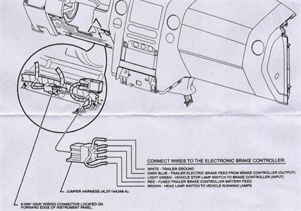
Troubleshooting Reese Pod Brake Controller Indicator Light ... The Reese Pod brake controller should be connected as follows. White - Ground Black - 12 Volt Constant Power Red - Cold Side of the Brake Pedal Switch Blue - Trailer Brake feed to Trailer Brakes If you are correctly wired and you are still experiencing problems, I would start with the following test. Start by disconnecting the blue brake feed ...

Pod brake controller wiring diagram
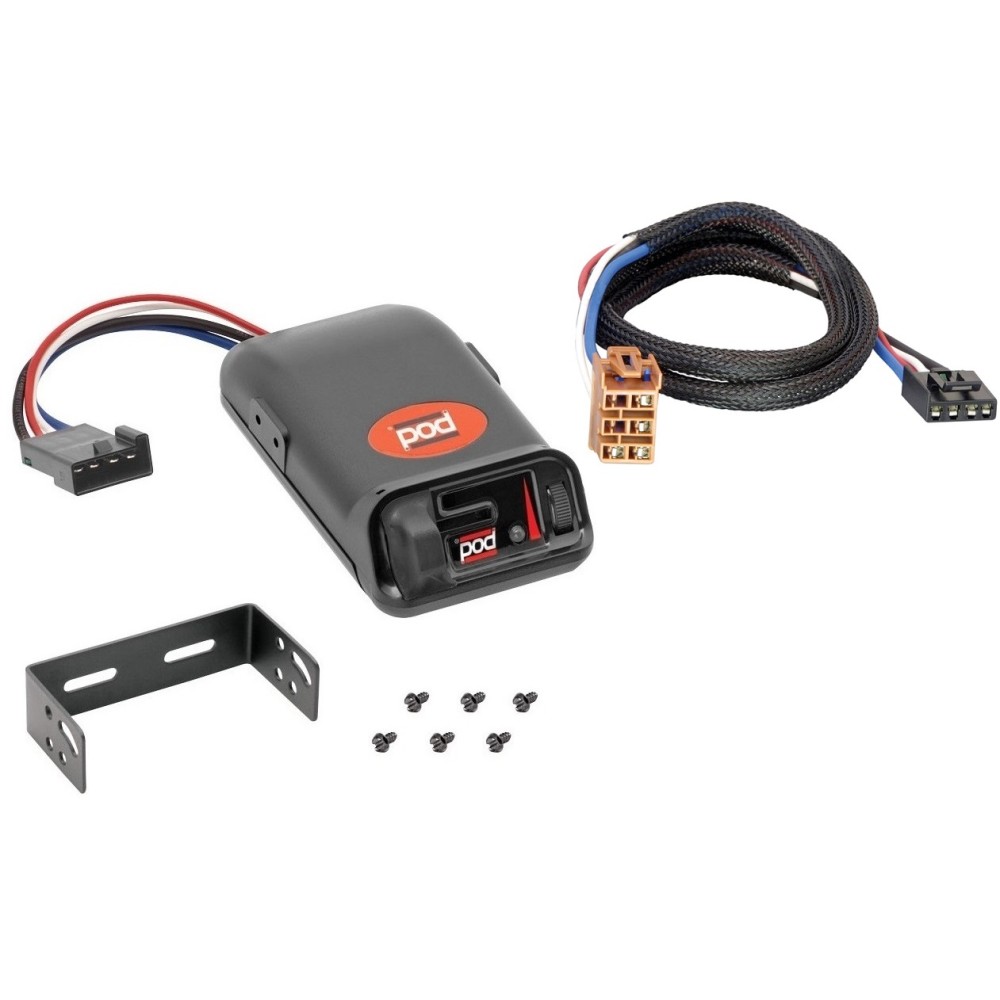
Installation Instructions for a Pod Brake Controller | It ... Step 1. Connect the supplied pigtail wiring harness into the electrical connection port on the rear of the pod brake controller. Purchase a wiring harness specific to your vehicle application from your vehicle's manufacturer, and plug that harness into the recommended connection portal. Place the pod controller inside the cab of the vehicle ... Tekonsha Primus Iq Installation Instructions - U Wiring Tekonsha Primus Iq Wiring Diagram wiring diagram is a simplified up to standard pictorial representation of an electrical circuit. Brake Control Attachment Locations 1. This connector allows you two options to wire your Brake Control. 6 x 38 Screws C. Primus IQ Trailer Brake Controller Proportional 1 to 3 Axles. PDF Instructions for Pod Brake Control Instructions for Pod® Brake Control READ THIS FIRST: Read and follow all instructions carefully before installing or operating the Brake Control. Keep these instructions with the Brake Control for future reference. D B C A Installation Guide A. Mounting Bracket B. #6 x 3/8" Screws C. Mounting Holes A C B P/N 7760 REV G NOTE: 1.
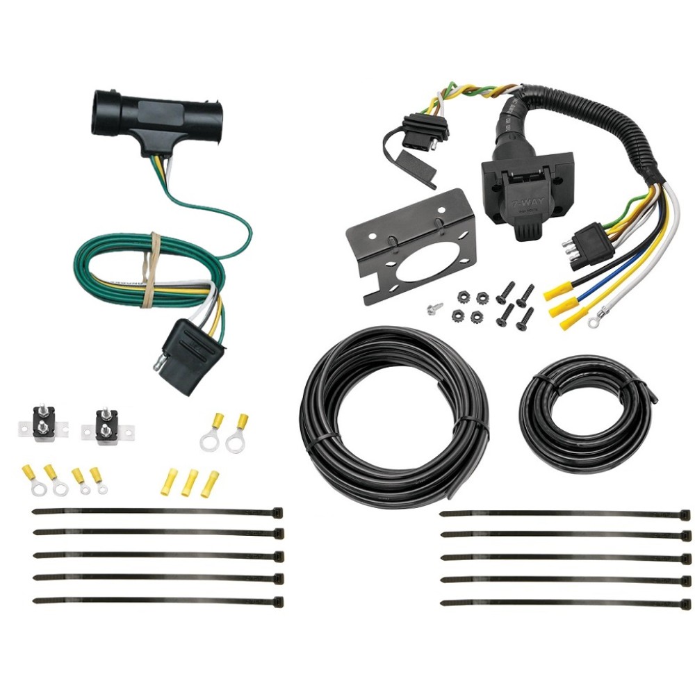
Pod brake controller wiring diagram. 2006 chevy silverado trailer brake controller installation ... IOT Wiring Diagram. No power to trailer brake controller chevy gmc control install how a on voyager wiring diagram where does plug into billavista com in installing an electric tow electronic can harness installation tekonsha prodigy 2006 silverado factory diy page sku for 03 07 reliance u haul curt 51352 quick reese pod 06 troubleshooting 2003 3500 sierra and 2500 2000 2018 oem hopkins simple ... Reese Pod Brake Controller Wiring Diagram - easywiring Sep 30, 2021 · Place the pod controller inside the cab of the vehicle near its. Hayman reese electric brake controller wiring diagram wiring diagram is a simplified tolerable pictorial representation of an electrical circuit it shows the components of the circuit as simplified shapes and the capacity and signal contacts between the devices. Reese Electrical Brake Control Systems Pod Electronic Brake Control, for 1 to 2 Axle Trailers . $42.95. Break Away Kits | Brake Control Wiring Harnesses BRAKE CONTROLLER INSTALL KITS: Part # Description. Price . Buy Now: 20505: Wiring Kit for 2 to 4 Brake Control Systems, Includes 25 ft. 12-2 Duplex Wire, 20 Amp Circuit Breaker and Attaching Terminals ... Tekonsha Pro Series POD® Trailer Brake Controller, Timed ... This item: Tekonsha Pro Series POD® Trailer Brake Controller, Timed, 1 to 2 Axles. $36.30. In Stock. Ships from and sold by Amazon.com. FREE Shipping. Tekonsha 3035-P Brake Control Wiring Adapter for Ford. ... RED WOLF Trailer Brake Controller Wiring Harness Connector Adapter Compatible with 2004-2020 Nissan Froniter/Titan/Armada, 2004-2017 ...
Electric Brake Controller Wiring Diagram : Elecbrakes Electric Brake Controller Wiring Diagram. Wiring Diagram. Auxiliary connection is optional, it may be connected to any 12v to 24v constant power source or left unconnected. Break away systems may be added to the service brake circuit. Elecbrakes is designed to operate 1 to 2 braked axles. Get. reese trailer brake controller wiring - More Trails, More ... Reese Pod Brake Controller Wiring Diagram tip wiringall.com. Buy Now: Wiring Kit for 2 to 4 Brake Control Systems, Includes 25 ft. Duplex Wire, 20 Amp Circuit Breaker and Attaching Terminals. $ Wiring Kit for 6 to 8 Brake Control. Brake Controllers. Pod Point Wiring Diagram - U Wiring Oct 14, 2021 · Wiring Diagram For Reese Pod Brake Controller. Typically it utilizes black black red and white cable colours. Your plug-in vehicle will have either a type 1 or type 2 AC socket so youll need to make sure your charging cable has the equivalent connector. The red one is. Nest Doorbell Wiring Diagram - Wiring Sample Nest hello wiring diagram for battery operated wired doer bell uk. Connect the wires to your nest doorbell. We ll run through the most common wiring example for replacing a front doorbell with nest hello if your doorbell wiring is different don t worry the app has. In this case it doesn t matter which wire goes where.
Tekonsha | 80500 | POD® Trailer Brake Controller, Timed, 1 ... The POD® needs to have a complete circuit on the Blue wire to the brake magnets then to ground for the Green LED to come on. Possible Causes: No trailer connected. No power on Black wire of control. Poor or on White wire of control. Open on electric brake wire (Blue wire). Open on the ground wire of the brake circuit. Power back feed on Blue wire. Brake Controller Installation: Starting from Scratch ... @JonG I have a 2020 Dodge durango. I have to hard wire my brake controller in. On my wiring harness for the brake it has 2 12 gauge wires black and blue and 16 gauge red and white. On your wiring diagram it says to use 12 gauge or higher. Should I match the wires according to my wiring harness or use 12 gauge on all? Installing Hayman Reese Brake Controllers and Wiring ... Presented by Hayman Reese technical towing expert Gary Gardiner, watch the typical installation process of Hayman Reese Brake Controllers, including end-to-e... Brake Controller - r-pod Nation Forum - Page 1 Brake Controller. We have a new 177--have taken two trips so far, both successful for most part. Love the R-Dome, though it did get 'airborne' first night when it was not staked well enough. We went through the mountains of Western North Carolina into South Carolina last week and the brakes on the trailer quit working about 150 miles from home.

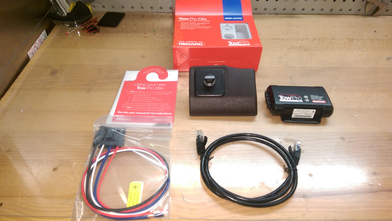
REDARC Tow-Pro Elite Wiring Kit for Mitsubishi Pajero TPWKIT-009
Wiring Diagram For Reese Pod Brake Controller Brake Controller Installation Starting From Scratch Etrailer Com. Trailer brake control wiring diagram controller installation starting troubleshooting 80500 accu power pod controls reese towpower 74377 break harness controllers for 99 02 chevy pro install write up 7437711 hidden the 7 best rvs 05 towing 7894 tekonsha rv plug 3500 and brakeman compact technical electrical oem page 3 ml350 ...
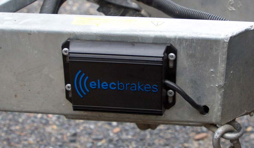
Elecbrakes | Bluetooth Electric Brake Controllers %%sep ...
Accupower Brake Controller Wiring Diagram - REVERSEITWELL 737 400 Air Conditioning System Schematic Diagram . Accu Power Pod Brake Controller . Acdelco 15926102 Gm Original Equipment Trailer Brake Control Switch Assembly . Reese Pod Wiring Diagram Wiring Diagram . Endless Brake Pads Set Circuit Compound Cc35 Type E N84m Alcon Ap Racing Caliper Cp6060 6065 6075 6080 Rcp072
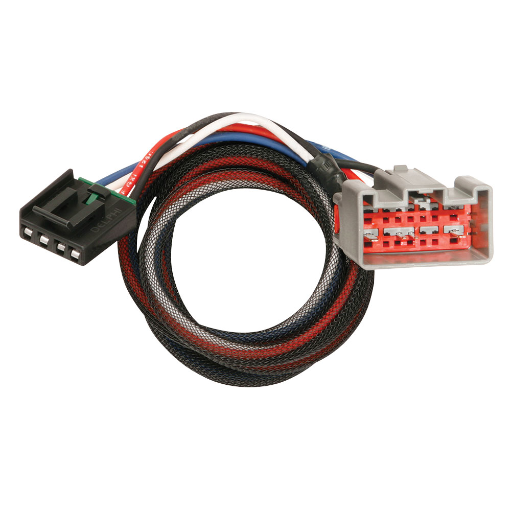
Tekonsha 3036-P Trailer Brake Control Wiring Harness - 2 Plugs, Ford
reese pod brake controller troubleshooting - Wiring ... Green Light No Longer Shown On Reese Pod Brake Controller Etrailer Com. Reese Towpower 74377 Pod Trailer Brake Controller Timed 1 To 2 Axles. The 7 Best Brake Controllers For Rvs Rv Care Bayside. ... ← Central Lock System Wiring Diagram Wiring Diagram For Ford F150 Radio ...

Tekonsha | Timed Controllers
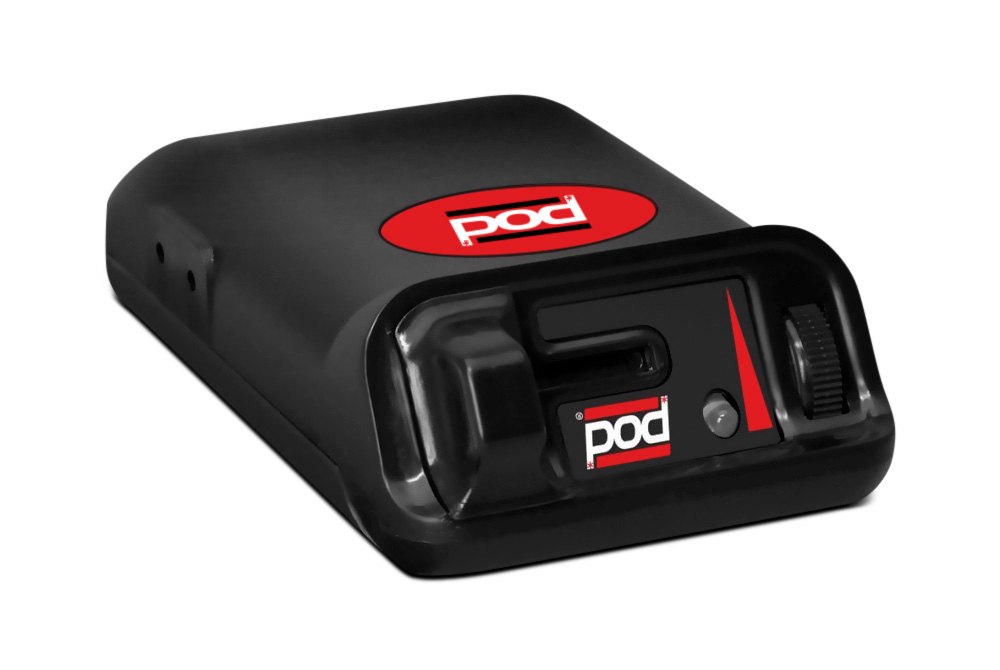
POD Brake Control for 1 & 2 Axle Trailers - Draw-Tite POD Brake Control for 1 & 2 Axle Trailers - POD Brake Control for 1 & 2 Axle Trailers - #80500 Features Include: Solid State Electronics Power-on LED Light for a positive tow ...
Prodigy Wireless Brake Controller - Forest River Forums
PDF Wiring instructions For ElEctronic BrakE controls The brake control must be installed with a 12 volt negative ground system. (To install with a positive ground system use Tekonsha ® P/N 3191.) 2. WARNING Reversing BLACK and WHITE wires or improper wiring will damage or destroy brake control. 3. WARNING Be sure to solidly connect all four wires or brake control will not function properly. 4.
09-20 E150 E250 E350 E450 08-16 F250 F350 F450 F550 Trailer ...
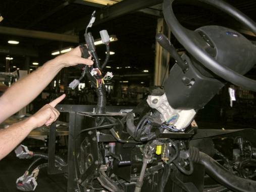
Trailer Brake Controller Installation How-To - 5 Easy Steps! Installing a brake controller involves disconnecting the vehicle battery, mounting the brake controller onto dash and plugging the unit in with a vehicle-specific wiring harness. If your vehicle is not equipped with a plug-and-play harness, you can also splice in wiring for connecting a brake controller. In this guide, we cover step-by-step how to install a brake controller.
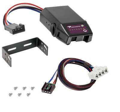
Trailer Brake Control for 95-09 Dodge RAM 1500 2500 3500 Wiring Tekonsha Voyager | eBay
Amazon.com: Reese Towpower 7437711 Pod Brake Control ... The Reese Towpower Pod Brake control is your best choice for one or two axle trailer, especially when your installation options are limited. The controller features solid state electronics, power-on LED for a positive tow vehicle-to-trailer connection and up-front manual over-ride controls.
The Best Trailer Brake Controllers and Why You Need One, 2022 ...
Reese Pod Brake Controller Wiring Diagram – Wiring Sample Jan 29, 2022 · Connect the supplied pigtail wiring harness into the electrical connection port on the rear of the pod brake controller. Place the pod controller inside the cab of the vehicle near its. Presented by hayman reese technical towing expert gary gardiner watch the typical installation process of hayman reese brake controllers including end to e.

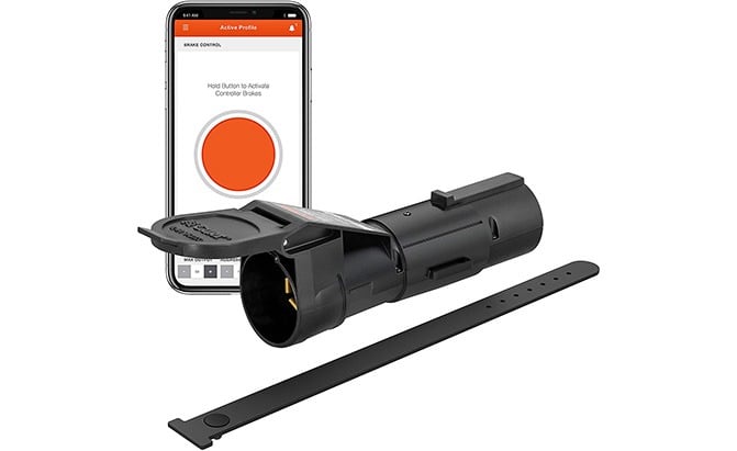
Portable Electric Brake Controller | GET TOWING IN 5 MINUTES ...
PDF Brake Control Wiring Diagram - AnythingTruck.com The brake control must be installed with a 12 volt negative ground system. (To install with a positive ground system use Tekonsha ® P/N 3191.) 2. WARNING Reversing BLACK and WHITE wires or improper wiring will damage or destroy brake control. 3. WARNING Be sure to solidly connect all four wires or brake control will not function properly. 4.
12-15 Mercedes GL350 450 550 and ML350 Trailer Brake Control ...
reese pod brake controller troubleshooting - IOT Wiring ... Green Light No Longer Shown On Reese Pod Brake Controller Etrailer Com. Reese Towpower 74377 Pod Trailer Brake Controller Timed 1 To 2 Axles. The 7 Best Brake Controllers For Rvs Rv Care Bayside. ... ← Auto Gate Motor Wiring Diagram Pdf 2005 Honda Accord Headlight Wiring Diagram ...

Trailer Wiring and Brake Control Wiring For Towing Trailers
Seymour Duncan Liberator Wiring Diagram - easywiring Wiring Diagram Reese Pod Brake Controller Wiring Diagram. Wiring Diagram 3 Phase Switch Wiring. Wiring Diagram Download Honda Trail Ct90 Wiring Diagram Pictures. Leave a Reply Cancel reply. Your email address will not be published. Required fields are marked * Comment. Name * Email * Website.
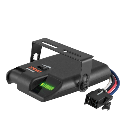
Trailer Brake Controllers | Proportional, Time Based, Wiring
PDF Instructions for Pod Brake Control Instructions for Pod® Brake Control READ THIS FIRST: Read and follow all instructions carefully before installing or operating the Brake Control. Keep these instructions with the Brake Control for future reference. D B C A Installation Guide A. Mounting Bracket B. #6 x 3/8" Screws C. Mounting Holes A C B P/N 7760 REV G NOTE: 1.
Trailer Brake Control for 99-02 Chevy Silverado 1500 2500 ...
Tekonsha Primus Iq Installation Instructions - U Wiring Tekonsha Primus Iq Wiring Diagram wiring diagram is a simplified up to standard pictorial representation of an electrical circuit. Brake Control Attachment Locations 1. This connector allows you two options to wire your Brake Control. 6 x 38 Screws C. Primus IQ Trailer Brake Controller Proportional 1 to 3 Axles.
Brake control install write up. | Tacoma World
Installation Instructions for a Pod Brake Controller | It ... Step 1. Connect the supplied pigtail wiring harness into the electrical connection port on the rear of the pod brake controller. Purchase a wiring harness specific to your vehicle application from your vehicle's manufacturer, and plug that harness into the recommended connection portal. Place the pod controller inside the cab of the vehicle ...
Towing a Trailer? Let's Talk About Brake Controllers ...
73-84 Chevy Blazer Suburban GMC Jimmy C/K Pickup 7 Way RV ...
Tekonsha Brake Controller Install! Super "Easy" | 2019+ Ford ...
Oem Trailer Brake Controller | Page 3 | Chevy Colorado & GMC ...
Oem Trailer Brake Controller | Page 3 | Chevy Colorado & GMC ...

Activator® IV Electronic Brake Control, for 1 to 4 Axle ...
BillaVista.com-Trailer Brake Controller Tech Article by ...

Tekonsha Trailer Brake Controller Install
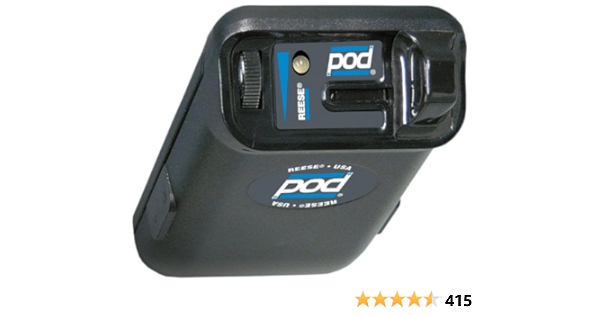
Amazon.com: Reese Towpower 74377 Pod Brake control, Black ...
Winnebago 2007 and Newer Ford and Workhorse Class A Chassis ...
The Best Trailer Brake Controllers and Why You Need One, 2022 ...

Accu-Power Pod Brake Controller

Products – Tagged "Brake Controllers" – Electric Brakes Australia
SHOP BRAKE CONTROLLERS IN CANADA.

Electric Brake Control Wiring | Trailer wiring diagram ...

TECHNICAL TECHNICAL ELECTRICAL BRAKE CONTROLS | Manualzz
Hidden Trailer Brake Controller install (pics) | Tacoma World

Portable Electric Brake Controller | GET TOWING IN 5 MINUTES ...
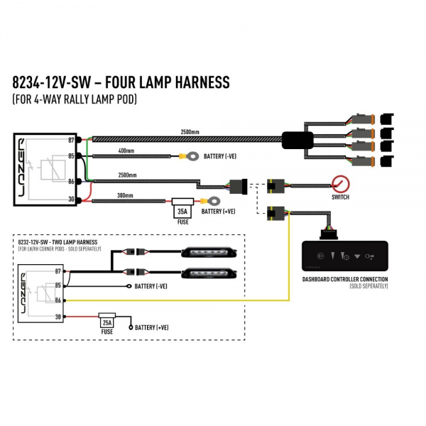
Four-lamp Wiring kit (Carbon Series)

POD TRAILER BRAKE CONTROL w/ ADAPTER FOR 2015-2019 SILVERADO SIERRA 2500 3500 | eBay

r-pod Bargman 7-pin Brake / Lights Adapter - R-pod Owners Forum

Brake Controllers

Brake Control Wiring Harness Tekonsha GM 99-02 - $13.90
Reese POD Trailer Brake Control for 05-16 Fleetwood Bounder ...
reese brake control wiring diagram Questions & Answers (with ...

Reese Towpower 7805011 Brake Control Wiring Harness

Details about Reese Towpower POD Brake Control 7437711
0 Response to "41 pod brake controller wiring diagram"
Post a Comment