40 delay on break timer wiring diagram
Time Delay on break for compressor - YouTube The time delay on break, how it works, how to wire into low voltage,and why you should have it on your compressor. Thanks for watching!- DavidDavid@DavidJone... ICM Controls ICM206 Delay On Break Timer, 4 Terminal with ... ICM Controls ICM102 DOM Timer, 10 Minutes Adjustable,Multicolor. 4.4 out of 5 stars. 124. 5 offers from $12.28. ICM Controls ICM203F Delay On Break Timer with .03-10 Minutes Adjustable Timing and 6 Lead Wires,Multicolor. 4.4 out of 5 stars. 40.
PDF Solid State Timers MARS Solid State Timers Delay On Break MARS solid state delay on break timers are designed to prevent short cycling of air conditioning, refrigeration and heat pump compressors. Upon application of power the load is energized. When the thermostat opens, or if there is a momentary loss of power, the load is de-energized and the delay period ...

Delay on break timer wiring diagram
Delay on Break Timer Time Delay Relays - Littelfuse Series Details. Order Samples. The KRPS Series is a factory programmed time delay relay available with 1 of 15 functions and measur... More. Input. Voltage (V): 12 or 48 V dc, 230 V ac, 24 or 240 V ac/dc. Output. Form: SPDT. Storage Temperature (F/C): -40° to 85°C (-40° to 185°F) PDF SSAC Timers & Controls Main Catalog - Steven Engineering Delay on Break (OFF-delay) Delay on Break (2 Terminal) Single Shot (Pulse Former) Single Shot (Motion Detector) Interval (Impulse ON) Interval (DC Volts Only) Interval (2 Terminal) Recycling (Delays Separately Adjustable) Recycling (Equal Delays) Delay on Make/ Delay on Break Delay on Make/Interval Other Functions Available Multifunction Time ... Delay On Break Timer Wiring Diagram For Your Needs Delay On Break Timer Wiring Diagram. Delay On Break Timer Wiring Diagram from i.ytimg.com. Print the cabling diagram off and use highlighters to trace the routine. When you make use of your finger or perhaps follow the circuit along with your eyes, it's easy to mistrace the circuit.
Delay on break timer wiring diagram. PDF Delay on Break Timer Relay - Airotronics Timing Mode: Delay on Break Type: Digital CMOS Time Range: 0.1 second to 24 hours Time Adjustments: Factory-fixed time period; variable, with adjustments on timer, or terminals for external resistor or potentiometer Repeatability: ±0.5% Setting Accuracy: Fixed time period: ±10% of nominal time. Variable time range: +15% -5% max. time, -10% min. time PDF Function diagrams - Crouzet of the time delay T. Output relay "R" (or the load) changes state at the end of this time delay. After opening of contact C (Y1), relay "R" drops out after a second time delay T. •At function: Timing on energisation with memory 1 relay Adds up the opening time of a contact. Output relay "R" (or the load) changes state at the end of timing. compressor time delay wiring diagram - Wiring Diagram Line compressor time delay wiring diagram Wiring Diagram Line Wiring Diagram. compressor time delay wiring diagram Wiring Diagram Line Wiring Diagram. Wiring Diagram Line We are make source the schematics, wiring diagrams and technical photos. ... 204 205 206 Icm Delay On Break Manualzz. Off Circuit On Timer Diagram [84DJC1] Circuit Diagram. The delay on break timer will release the lock and then the delay on make timer will enable the door to open and be held open for a set period of time. At the end of this off time, the output energizes and the on time begins. This is how the 555 Timer-based Power ON delay circuit works.
HVAC Delay On Make Timer (How it works & How To Wire ... Today we will go over what is a HVAC delay on make timer and how it works, how to wire the delay on make timer and when to use a delay on make time delay for... Delay On Break Timer Wiring Diagram Gallery - Wiring ... August 9, 2018. April 5, 2018 by headcontrolsystem. Variety of delay on break timer wiring diagram. A wiring diagram is a simplified traditional pictorial depiction of an electric circuit. It reveals the parts of the circuit as streamlined shapes, and the power as well as signal links between the devices. A wiring diagram generally provides details about the relative position as well as plan of devices and also terminals on the devices, in order to help in structure or servicing the gadget. ICM206 Delay on Break Timer (3-10 Minute Adjustable Delay) ICM Controls ICM206B - ICM206 Delay on Break Timer (3-10 Minute Adjustable Delay) - Delay on Break Timers ("anti-short cycle", "ON delay on break") helps to protect air conditioning, refrigeration and heat pump equipment from damage which may be caused by the rapid short cycling of compressors. Features Brownout protection UL 873 recognition as ... PDF Icm203 Icm203 - Icm Controls Time Time ICM 203 DELAY ON BREAK VPS00C 18-240 VAC, 2-Wire ANTI-SHORT CYCLE/ LOCKOUT TIMER MODE OF OPERATION INSTALLATION • Knob adjustable from .03-10 minutes • Works with anticipator type thermostats 1. Disconnect power. 2. Connect terminals in series with the starting device as shown in the wiring diagram below. 3. For 24 VAC circuits, apply control as
Delay On Break Timer Wiring Diagram Download - Wiring ... Name: delay on break timer wiring diagram - Here is the simple circuit diagram of a LED dimmer which reduces the intensity brightness of LED using PWM concept; File Type: JPG; Source: pinterest.co.uk; Size: 55.99 KB; Dimension: 736 x 535; Essential Tips for Safe Electrical Repairs Installing a Delay on Break timer - HVAC-Talk The delay on make timer is added to units to prevent them from coming on before the pressures equalize causing the fuses to blow or breaker to trip. Don't use "delay on make" timers for outdoor units, they are stupid pointless things, use "delay on break" timers. The planet is fine, the people are ! -George Carlin. PDF Electronic timer - Siemens • OFF delay timers are with aux. voltage (refer wiring diagram fig.1). Same potential must be applied to A1 and B1, or A3 and B3. • With the two-voltage version, only one voltage range must be connected. • The activation of loads parallel to the start input is not permissible when using AC control voltage (see diagram below). Mounting On Delay Timer | Off Delay Timer Working Principle ... On Delay Timer and off Delay Timer: Generally, timers are used to control the circuit for a certain amount of time. Using timers we can delay the circuit operation. Three types of timers are the most commonly used in the electric circuit. One is On-delay timer, the second one is off relay timer and the third one is star delta timer.
Using a Time Delay Relay to Control Disinfecting UV Light ...
PDF Timer - Delay-on-Make TDM / TDMH / TDML Series TIME DIAGRAM Example: Delay-on-Break (Release) Input Applied Off Output Energized (Normally De-energized Open) Initiate Closed Switch Open R = Reset TD = Time Delay S1 = Initiate Switch Undefined time t = Incomplete Time Delay Appendix A - Timer Functions

Cube Relay Delay On Break Timer - TGPB Timers From Airotronics
PDF ON Delay/OFF Delay ICM254 - ICM CONTROLS • OFF delay: 12-390 seconds INSTALLATION 1.Disconnect power. 2. Connect terminals as shown in the wiring diagram below. 3. Select desired delay on make and delay on break periods. 4. Reapply power, check operation. MODE OF OPERATION Power must be applied at all times. Upon closure of the thermostat, the delay on make period begins.

Mars - Adjustable Delay-On-Break Timer - Saez Distributors
Understanding Time Delay Relay Functions | Macromatic When the trigger is applied, the time delay (t1) begins and the output is energized for the time delay (t2). At the end of this time delay (t2), the output is de-energized and remains in that condition for the time delay (t2). At the end of the time delay (t2), the output is energized and the sequence repeats until time delay (t1) is completed.

203 ICM DELAY ON BREAK | Manualzz
PDF Td60 Series, Solid State Delay on Make Timers Technical ... installation diagram: * for all 120-240 volt pilot circuits, the wire jumper must be cut as shown timing diagram: input on input power input off voltage break voltage time load on time load time load energized off delay energized delay energized time k:\specific\td69_spc.doc control or pilot circuit voltage
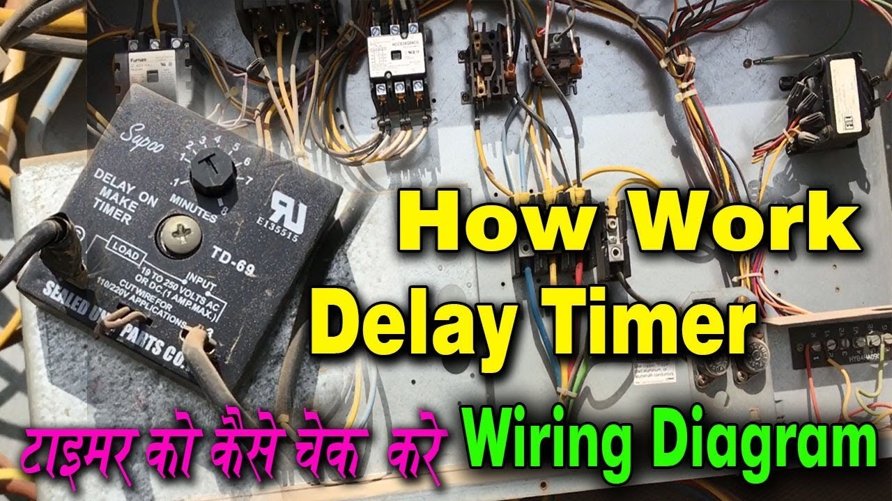
Time delay how work checking tips tricks wiring diagram everything learn in Hindi
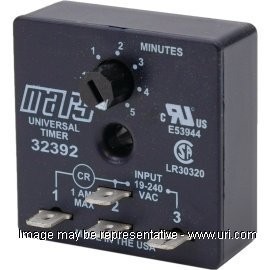
32392 - MARS 32392 - Adjustable Delay on Break Time Delay The MARS 32390 and the new 32505 are the most simple and economic ways to stop short cycling on 24 VAC controlled systems. Both devices are fixed 5minute delay on break timers. Features: 1 to 3 second random re-start. Models for two-wire or three-wire connection. Dial adjustable.

USA Supco Delay On Break Timer Relay TL243 3310-183 - North ...
ICS Time Delay Module Applications and Wiring Figure 1. The KH1 Series adjustable ON DELAY module connection diagram. View is from the flat side with the catalog numbers. Time delay is variable and dependent on the resistance value of Rt. Rt @ 0 Ohm = minimum delay, Rt @ 1M Ohm = maximum delay. Module LOAD at Pin 2 is a relay coil.
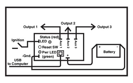
USB 12v Programmable Delay Timer | ACDC Industries
Wiring Diagram For Ckhkc Delay Timer 8 Pin Wiring Diagram For Ckhkc Delay Timer 8 Pin. If this is the first time you've come across Amiga Format, then k«0 WORDS 2 W PROCESSOR 1 8 > ; ' 1 1 h I AM l| 4; . 4 for 50 CITIZEN D+ 80 COLUMN, 9 PIN CPS25NLQ 24 Its complexity and release delays may have fatally wounded its chart chances. Note: For details, refer to Precautions for H3Y-series Timers on page Socket Pin.

HVAC Delay On Make Timer (How it works & How To Wire) Compressor Staging/Startup Delay Timer
Delay on Break Timers - Airotronics Off Delay, Delay on Release, Delay on De-Energization Delay on Break. Power is continuously applied to the input terminals of the timer. Upon closure of a Normally Open (N.O.) external initiate switch, the load transfers immediately and remains transferred as long as the external initiate switch is closed.

ICM203 - ICM Controls ICM203 - ICM203 Delay on Break Timer ...
Delay On Break Timer Wiring Diagram - Free Wiring Diagram delay on break timer wiring diagram DOWNLOAD. DOWNLOAD. Assortment of delay on break timer wiring diagram. Click on the image to enlarge, and then save it to your computer by... A Novice s Overview to Circuit Diagrams. A very first look at a circuit representation could be complex, however if ...

How to wire Dayton Off Delay Timer
Simple Delay Timer Circuits Explained - Homemade Circuit ... In this post we discuss the making of simple delay timers using very ordinary components like transistors, capacitors and diodes. All these circuits will produce delay ON or delay OFF time intervals at the output for a predetermined period, from a few seconds to many minutes. All the designs are fully adjustable.

Implementing Hardware Switch Debounce | DigiKey
On-Delay Relays | McMaster-Carr The delayed switch-off (delay-on-break) function uses a switch instead of input voltage. When the switch is turned off, the relay remains on for a programmed amount of time before turning off. For example, a projector's light is turned off with a switch, but its cooling fan continues to run for a set time.

TGCMLB | Delay on Make/Delay on Break Relay Timer Dual Function
Delay On Break Timer Wiring Diagram For Your Needs Delay On Break Timer Wiring Diagram. Delay On Break Timer Wiring Diagram from i.ytimg.com. Print the cabling diagram off and use highlighters to trace the routine. When you make use of your finger or perhaps follow the circuit along with your eyes, it's easy to mistrace the circuit.
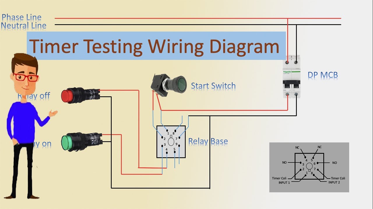
Timer Testing Wiring Diagram | Timer | Timer Wiring | Timer Wiring
PDF SSAC Timers & Controls Main Catalog - Steven Engineering Delay on Break (OFF-delay) Delay on Break (2 Terminal) Single Shot (Pulse Former) Single Shot (Motion Detector) Interval (Impulse ON) Interval (DC Volts Only) Interval (2 Terminal) Recycling (Delays Separately Adjustable) Recycling (Equal Delays) Delay on Make/ Delay on Break Delay on Make/Interval Other Functions Available Multifunction Time ...

ICM203
Delay on Break Timer Time Delay Relays - Littelfuse Series Details. Order Samples. The KRPS Series is a factory programmed time delay relay available with 1 of 15 functions and measur... More. Input. Voltage (V): 12 or 48 V dc, 230 V ac, 24 or 240 V ac/dc. Output. Form: SPDT. Storage Temperature (F/C): -40° to 85°C (-40° to 185°F)

How to wire on delay timer
Overview of Timers | OMRON Industrial Automation

How to wire on delay timer

Delay On Brake Timer – Everwell Parts Inc.

USA Watsco ICM Delay On Break Timer Relay EAC 650

207/208/209 ICM DELAY ON BREAK APS | Manualzz
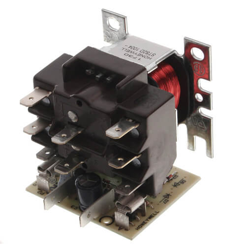
ST82D1004 - Honeywell ST82D1004 - Time Delay Relay w/ DPDT ...

Solid-State Output Delay On Break Timers - TH3ML Timers From ...
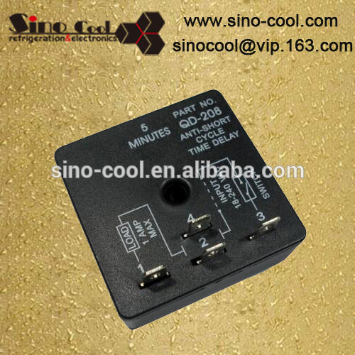
QD-208 Delay On Break Timer - Coowor.com

How to wire on delay timer
Shop Solid State Short Cycle Delay Timers - URI

Solid-State Output Delay On Break Timers - TH3M Timers From ...

Cube Relay Delay On Break Timers - TGMVB Timers From Airotronics

HOW IT WORKS|DELAY ON BREAK TIMER

ICM Controls ICM253 Fan Delay Timer, 12-390 Seconds ...
Delay On Break Timer

Cube Relay Delay On Break Timers - TGMB Timers From Airotronics

ICM Controls ICM203 Delay on Break Timer, 18-240 Vac, 1.25 ...
ICM254

AH3 delay timer and relay | Timer, Electrical circuit diagram ...

Time-Delay Electromechanical Relays Worksheet - Digital Circuits

20 Most Recent Amperite Dayton Solid State Timer On Questions ...
Air assist - Delay Relay - LightBurn Hardware Compatibility ...

Relay Wiring Diagram and Function Explained - ETechnoG
TIME DELAY RELAYS

Delay On Break Timer QD-072 EQV.SUPCO Timer Relay
0 Response to "40 delay on break timer wiring diagram"
Post a Comment