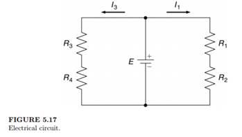
40 consider the circuit depicted in the diagram
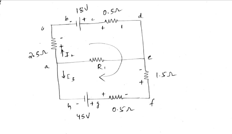
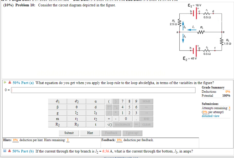
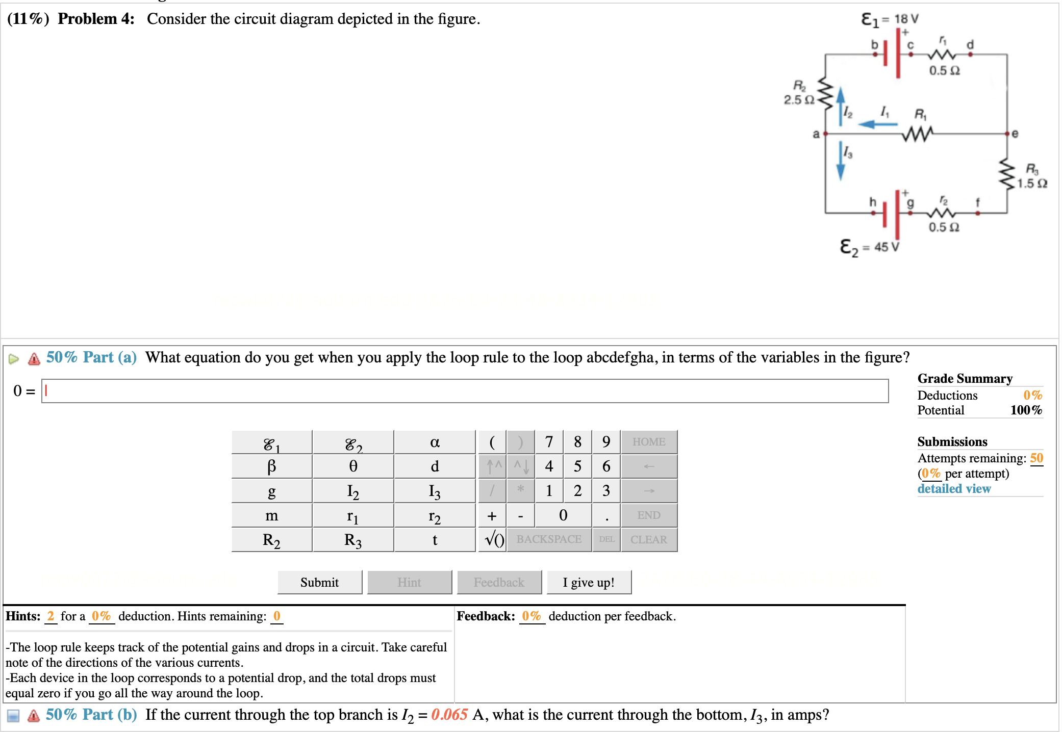
PDF Module 4 Electronic Diagrams and Schematics - Energy Figure 3 Example of an Electronic Schematic Diagram A second type of electronic schematic diagram, the pictorial layout diagram, is actually not so much an electronic schematic as a pictorial of how the electronic circuit actually looks. These drawings show the actual layout of the components on the circuit board. Answered: Problem 7: Consider the circuit diagram… | bartleby Solution for Problem 7: Consider the circuit diagram depicted in the figure. E= 18 V 0.5 0 R 2.5n 4 R, R 1.52 0.50 E, = 45 V
Voltage in Series and Parallel - Making Easy Circuits The electric potential difference of various spots in the circuit may be depicted by using a diagram known as electric potential diagram which is demonstrated underneath. In this illustration, the electric potential at A is = 9V because it's the bigger potential point. The electrical potential at H is = 0V because it is at negative point.
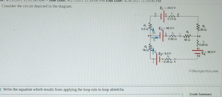
Consider the circuit depicted in the diagram
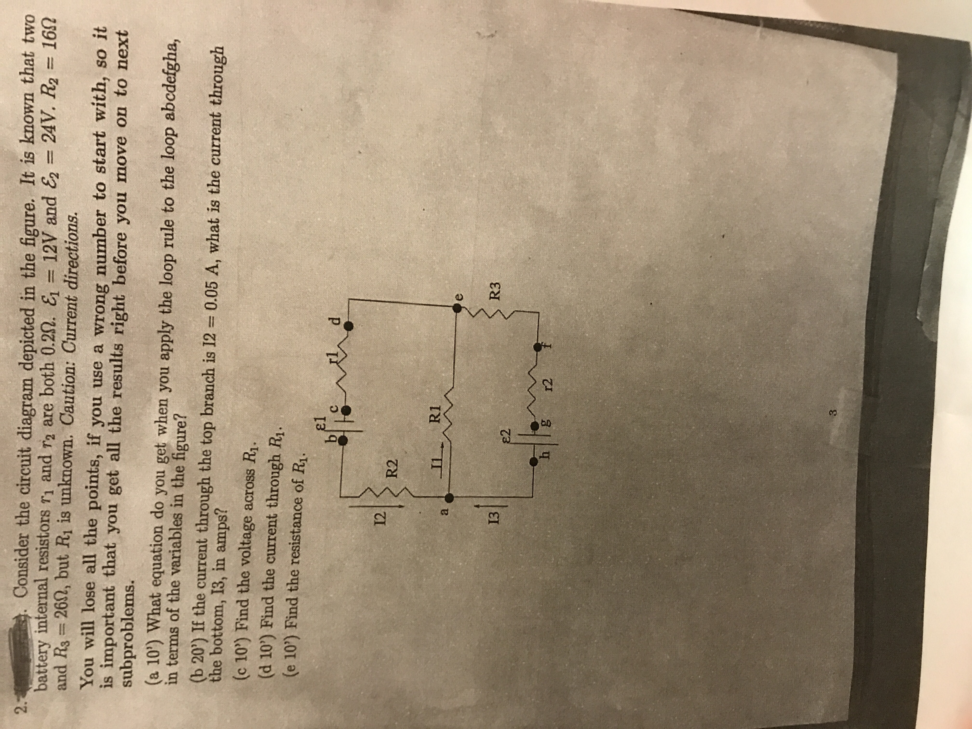
Consider the circuit diagram depicted in the figure. (a ... Answer to: Consider the circuit diagram depicted in the figure. (a) What equation is obtained when the loop rule is applied to the loop abcdefgha,... Answered: Consider the circuit diagram depicted… | bartleby Consider the circuit diagram depicted in the fgure. It is known that two battery internal resistors r1and r2 are both 0.2Ω· = 12V and & = 24V. R2 16Ω 2. and Rs 262, but Ri is unknown. Caution: Current directions. PDF Final Exam - University of Utah Problem 4: [Digital Logic] Consider the circuit depicted in Fig. 4 that is being used as an inverter. For the transistor, V tn = 1 V, µ n = 5 × 10− 2m /Vs, C ox = 2×10⁻³ F/m2, and W L = 10. You may ignore channel length modulation effects. [10 points] (a) What are the high and low logic levels at the output (V OH and V OL),
Consider the circuit depicted in the diagram. Consider the circuit shown in the figure. All the ... Click here👆to get an answer to your question ️ Consider the circuit shown in the figure. All the resistors are identical. Find the ratio II' . Solved > Question Consider the circuit diagram depicted in ... What equation : 646641. Consider the circuit diagram depicted in the figure. What equation do you get when you apply the loop rule to the loop abcdefgha, in terms of the variables in the figure? 0 = If the current through the top branch is I_2 = 0.69 A, what is the current through the bottom, I_3, in amps? Solved > Question Consider the circuit below, find the ... Question Consider the circuit diagram consisting of capacitors and a battery pictured on the board. Find the equivalent capacitance, the charge on each capacitor and the... Question Consider the circuit diagram depicted in the figure. What equation do you get when you apply the loop rule to the loop abcdefgha, in terms... What is Capacitive Circuit? Formula & Function | Linquip Consider the circuit in the diagram above, which consists solely of a capacitor and an AC power supply. It turns out that the current and voltage have a 90-degree phase difference, with the current reaching its peak 90 degrees (1/4 cycle) before the voltage does. An oscillating voltage is produced by the AC power supply.
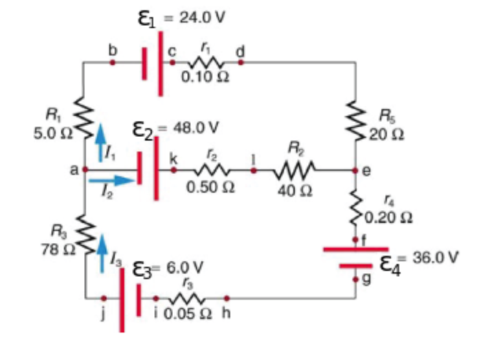
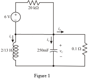
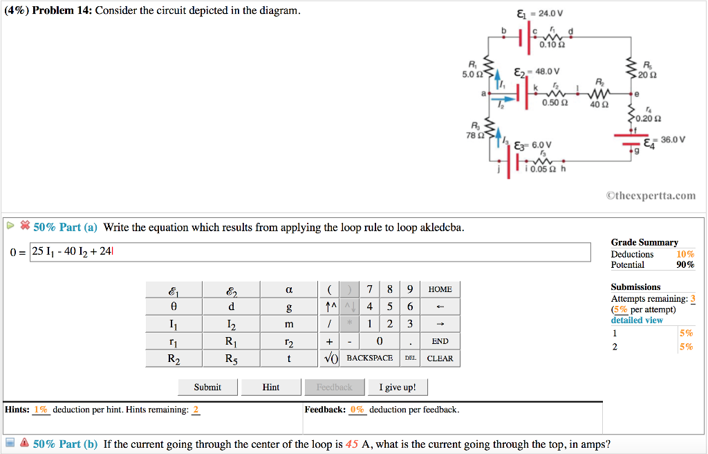
For the circuit shown in the figure, calculate (a) the ... For the circuit shown in the figure, calculate (a) the current in the 2.00-Ω resistor and (b) the potential difference between points a and b, ΔV = Vb - Va. Solved Consider the circuit diagram depicted in the figure ... Physics. Physics questions and answers. Consider the circuit diagram depicted in the figure. What equation do you get when you apply the loop rule to the loop abcdefgha? If the current through the top branch is I_2 = 0.49 A. what is the current through the bottom, I_3, in amps? Question: Consider the circuit diagram depicted in the figure. Answered: Problem 1: Consider the circuit… | bartleby Problem 1: Consider the circuit depicted in the attached figure. The voltage source is an AC source of frequency f = 55 Hz. R, Randomized Variables C, R1 = 103 Q R2 = 162 Q C1 = 6.5 µF C2 = 9.5 µF V C2 R2 L = 0.77 H Part (a) Given the above circuit, write an expression for the total impedance Z for the circuit as a complex number. Solved Consider the circuit depicted in the diagram ... Physics. Physics questions and answers. Consider the circuit depicted in the diagram. (a) Write the equation which results from applying the loop rule to loop akledcba. (b) If the current going through the center of the loop is 65 A, what is the current going through the top, in amps? Question: Consider the circuit depicted in the diagram. (a ...
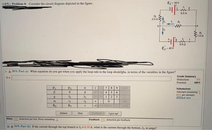
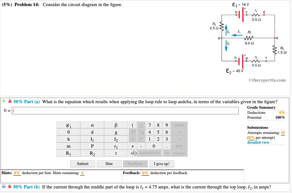
Answered: ENL Consider the circuit diagram… | bartleby ENL Consider the circuit diagram depicted in the figure. E- 18 V 0.50 250 ww 1.50 0.50 (a) What equation do you get when you apply the loop rule to the loop abedefgha, in terms of the variables in the figure? (b) If the current through the top branch is /037 A, what is the current through the bottom, I, in amps? sin tan. PDF Chapter 28 Draw the circuit diagram and assign labels and symbols to all known and unknown quantities. Assign directions to the currents. The direction is arbitrary, but you must adhere to the assigned directions when applying Kirchhoff's rules Apply the junction rule to any junction in the circuit that provides new relationships among SOLVED:%o ) Problem 4: Consider the circuit diagram ... %o ) Problem 4: Consider the circuit diagram depicted in the figure. E1= 18V 0.5 Q 25 0 1,5 0 0.5 4 82 45V 50 % Part (a) What equation do yOu get when YOu apply the loop ule to the loop abcdefgha _ in terrns of the variables in the figure? Wk10a.pdf - The Expert TA | Human-like ... - Course Hero I 3 = _____ Problem 3: Consider the circuit depicted in the diagram. 4/6/2018 The Expert TA | Human-like Grading, Automated! 2/2 Part (a) Write the equation which results from applying the loop rule to loop akledcba.
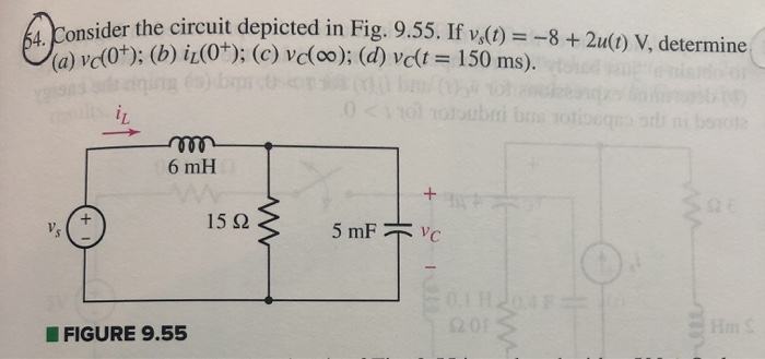
Solved 6. Consider the circuit depicted in Fig. 9.55. If ...
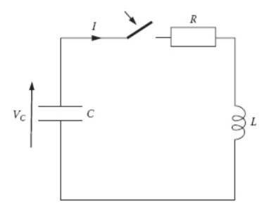
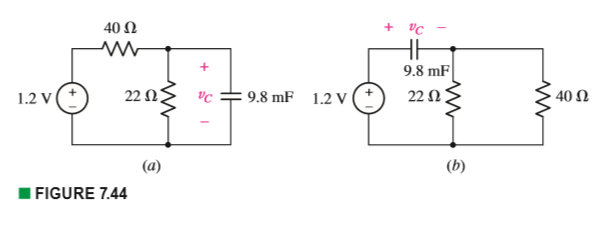
Parallel RC circuit analysis - Student Circuit Parallel RC circuit analysis. This post tells about the parallel RC circuit analysis. RC circuits belong to the simple circuits with resistor, capacitor and the source structure. Let's consider the circuit depicted on the figure below. We have to remember that even complex RC circuits can be transformed into the simple RC circuits.
Solved Consider the circuit depicted in the diagram. If the ...
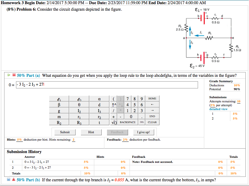
(10) Problem 1 Consider the circuit diagram depicted in ... (10%) Problem 1: Consider the circuit diagram depicted in the figure. <1.592 0.50 45 V A 50% Part (a) What equation do you get when you apply the loop rule to the loop abcdefgha, in terms of the variables in the figure? > A 50% Part (b) If the current through the top branch is 12 = 0.83 A, what is the current
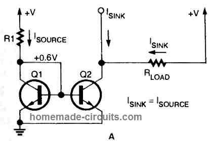
Exploring Current Mirror Circuits with Practical Designs ...
Physics Tutorial: Combination Circuits - Physics Classroom This is shown in Diagram B. Now that all resistors are in series, the formula for the total resistance of series resistors can be used to determine the total resistance of this circuit: The formula for series resistance is Rtot = R1 + R2 + R3 + ... So in Diagram B, the total resistance of the circuit is 10 Ω.
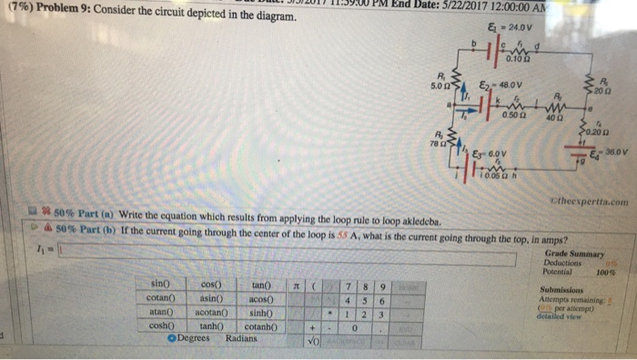
Solved (7%) Problem 9: Consider the circuit depicted in the ...
Consider the circuit diagram depicted in the figure ... Consider the circuit diagram depicted in the figure. What equation do you get when you apply the loop rule to the loop abcdefgha? If the current through the top branch is I_2 = 0.49 A. what is the current through the bottom, I_3, in amps? Answer 1. I will be glad to see your comment if you have any query…-1 3,01,-101, +27 2 *A 3,012-a.ng+2구 δ:
ECE/CS 3700: Fundamentals of Digital System Design
% Problem 30: Consider the circuit diagram in the figure ... View (3) Problem 30 Consider the circuit diagram in the figure. E1 = 18V.docx from AA 1 (3%) Problem 30: Consider the circuit diagram in the figure. E1 = 18V R Ez = 45 Otheexpertta.c 50% Part (a)

A Canonical Neural Mechanism for Behavioral Variability | bioRxiv
PDF Your Comments - University of Illinois Urbana-Champaign Consider the harmonically driven series LCR circuit shown. V max = 100 V I max =2 mA V Cmax =113 V The current leads generator voltage by 45o L and R are unknown. What is X L, the reactance of the inductor, at this frequency? Electricity & Magnetism Lecture 20, Slide 25
Get Answer) - The switch in the LRC oscillatory circuit shown ...
Consider the circuit diagram depicted in t... | Clutch Prep Problem Details. Consider the circuit diagram depicted in the figure. Part (a) What equation do you get when you apply the loop rule to the loop abcdefgha? Part (b) If the current through the top branch is I2 = 0.49 A, what is the current through the bottom I3, in amps? Learn this topic by watching Kirchhoff's Loop Rule Concept Videos.
Solved (14%) Problem 4: Consider the circuit diagram | Chegg.com
MasteringPhysics: Problem Print View - hi Now consider a diagram describing a parallel AC circuit containing a resistor, a capacitor, and an inductor. This time, the voltage across each of these elements of the circuit is the same; on the diagram, it is represented by the vector labeled .

Oscillatory recurrent gated neural integrator circuits ...
PDF Final Exam - University of Utah Problem 4: [Digital Logic] Consider the circuit depicted in Fig. 4 that is being used as an inverter. For the transistor, V tn = 1 V, µ n = 5 × 10− 2m /Vs, C ox = 2×10⁻³ F/m2, and W L = 10. You may ignore channel length modulation effects. [10 points] (a) What are the high and low logic levels at the output (V OH and V OL),
Asymmetric SATS driven by an external signal I. The results ...
Answered: Consider the circuit diagram depicted… | bartleby Consider the circuit diagram depicted in the fgure. It is known that two battery internal resistors r1and r2 are both 0.2Ω· = 12V and & = 24V. R2 16Ω 2. and Rs 262, but Ri is unknown. Caution: Current directions.
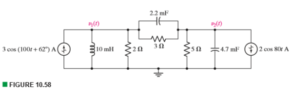
Solved) - For the circuit depicted in Fig. 10.58, (a) redraw ...
Consider the circuit diagram depicted in the figure. (a ... Answer to: Consider the circuit diagram depicted in the figure. (a) What equation is obtained when the loop rule is applied to the loop abcdefgha,...
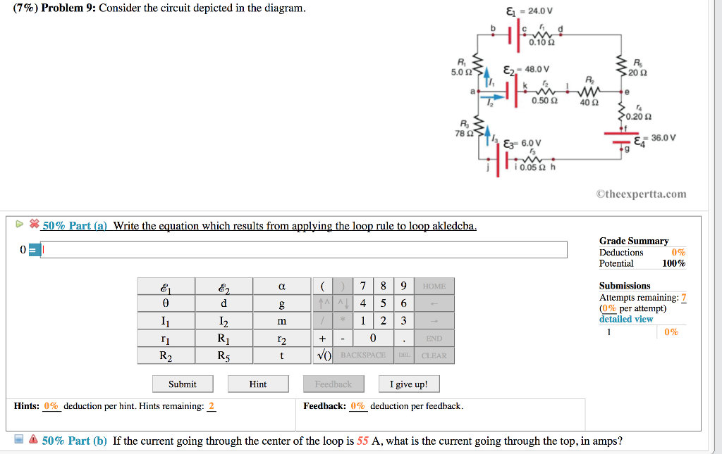
Solved (7%) Problem 9: Consider the circuit depicted in the ...
Solved: Consider the circuit depicted in Fig. 9.38. (a ...
Solved (5%) Problem 14: Consider the circuit diagram in the ...
Entropy | Special Issue : Nonlinear Dynamics and Entropy of ...
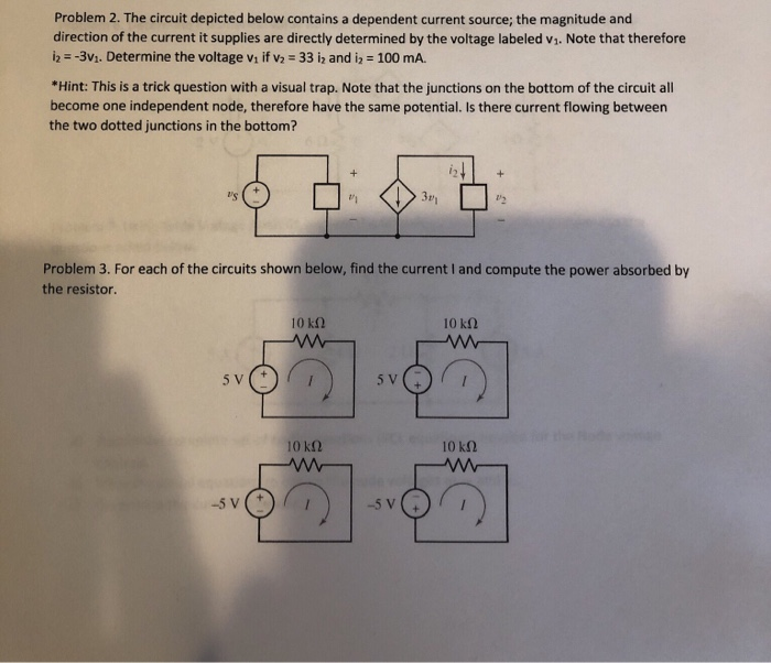
Solved Problem 2. The circuit depicted below contains a ...

Schematics of the detection setup equivalent to the high ...

State Transition Table - an overview | ScienceDirect Topics
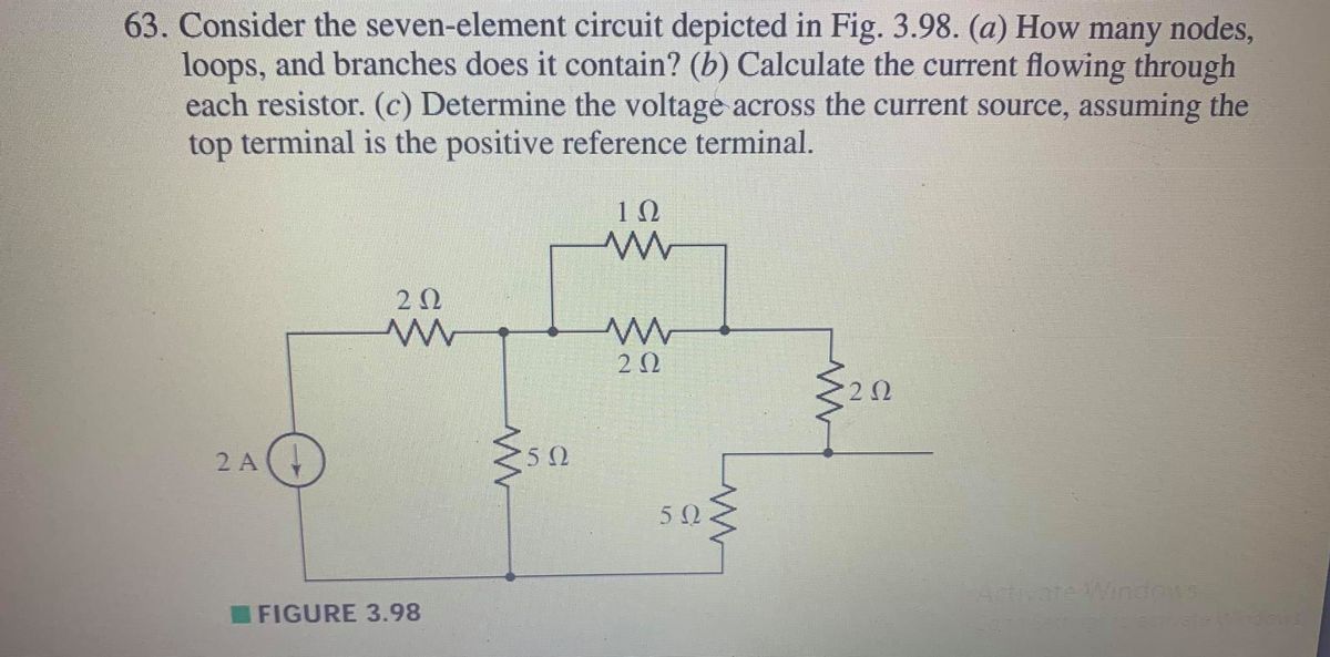
Answered: 63. Consider the seven-element circuit… | bartleby
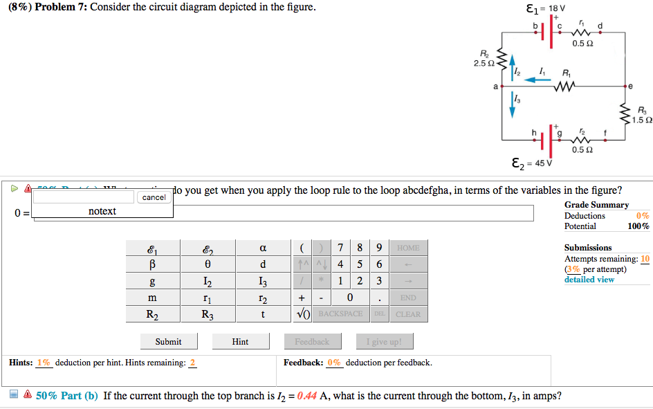
Solved (8%) Problem 7: Consider the circuit diagram depicted ...
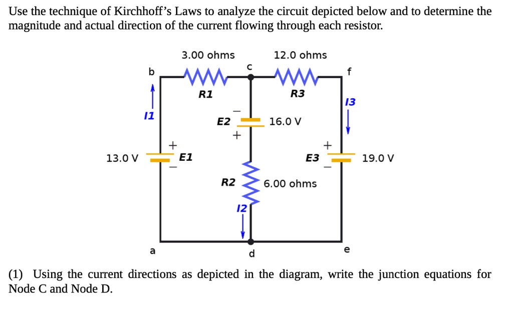
SOLVED:Use the technique of Kirchhoff's Laws to analyze the ...

Watt's Up?: May 2013

Please Help Meee.. Will give brainlest What is the total ...

Evolution of gate circuit parameters when considering both ...
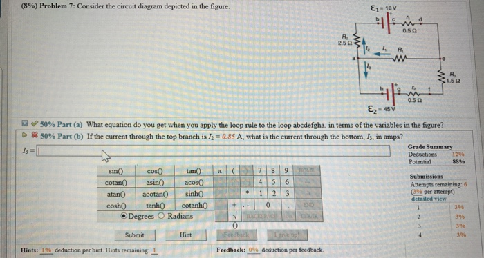
Solved (8%) Problem 7: Consider the circuit diagram depicted ...
Get Answer) - For the electrical circuit depicted in Figure ...
Solved (496) Problem 14: Consider the circuit depicted in ...
Answered: ENL Consider the circuit diagram… | bartleby
Answered: Consider the circuit diagram depicted… | bartleby
Solved (10%) Problem 10: Consider the circuit diagram | Chegg.com
Solved Date: 428/2021 11:59:00 PM Consider the circuit ...
Solved) - Calculate the power dissipated in the 40 ? resistor ...
Solved] 6. What, exactly, is a short circuit? What does it ...
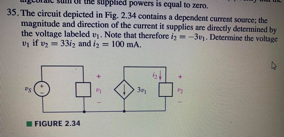
Answered: 35. The circuit depicted in Fig. 2.34… | bartleby
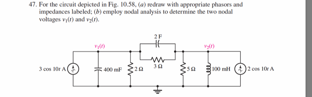
Solved 47. For the circuit depicted in Fig. 10.58, (a ...

Straight circuit (depicted in Fig. 2a): Time series of branch ...
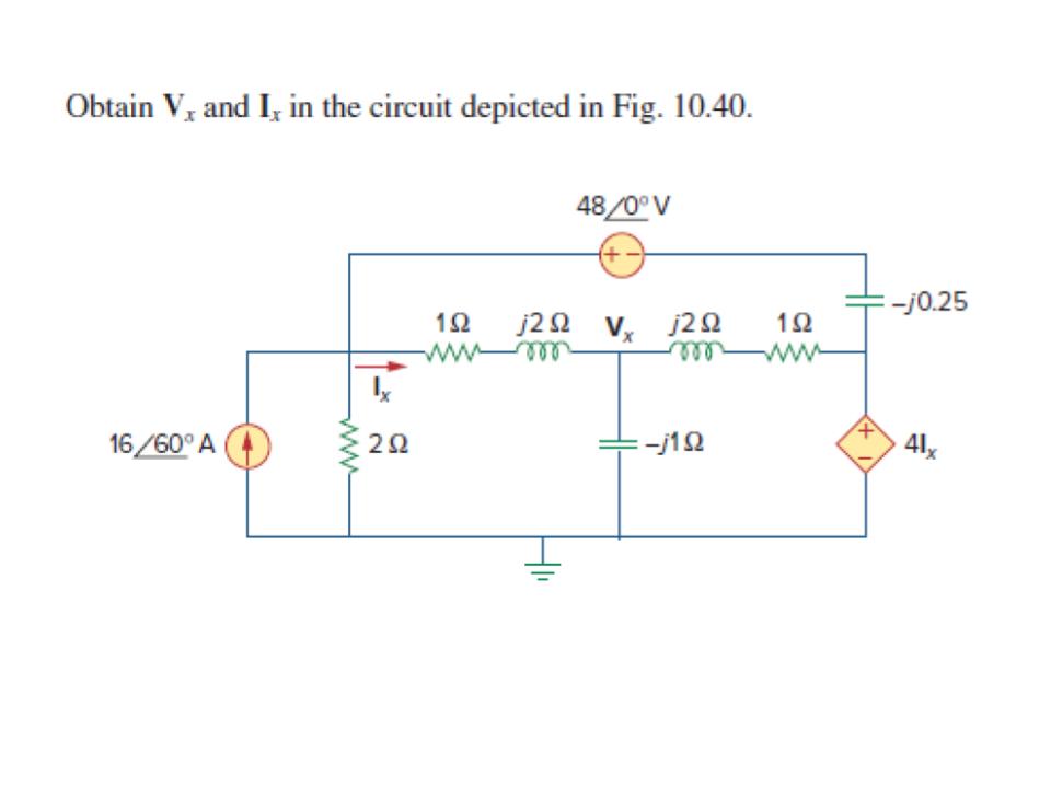
Answered: Obtain V, and I, in the circuit… | bartleby
Solved Consider the circuit diagram depicted in the figure ...
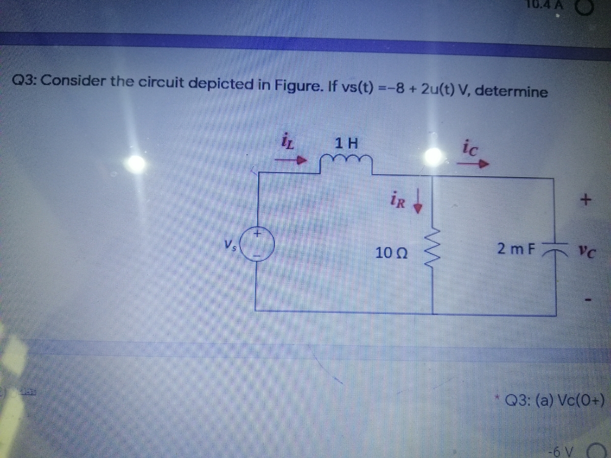
Answered: usider the circuit depicted in Figure.… | bartleby
Solved (11%) Problem 4: Consider the circuit diagram | Chegg.com
0 Response to "40 consider the circuit depicted in the diagram"
Post a Comment