39 alternating relay wiring diagram
› 2012 › 02Star Delta Starter - (Y-Δ) Starter Power, Control & Wiring ... Automatic Star / Delta Starter with Timer for 3-Phase AC Motors. In this tutorial, we will show the Star-Delta (Y-Δ) 3-phase induction AC Motor Starting Method by Automatic star-delta starter with Timer with schematic, power, control and wiring diagram as well as how star-delta starter works and their applications with advantages and disadvantages. Alternator Wiring Diagram: A Complete Tutorial | EdrawMax This is a three-wire alternating wiring diagram showing the connections between the different components of a circuit. The circuit comprises three main wires: battery positive cable, voltage sensing wire, and ignition wire. The ignition input wire is attached to the engine. It conducts electricity from the engine to the alternator while the ...
PDF D85 alternating relay instructions - Eaton Wiring Diagrams If the unit has the low-profile selector switch, set this switch to "ALTERNATE" for normal operation. In this mode, the unit will operate as a normal Alternating Relay, alternating between the two loads on each subsequent closing and opening of the control switch. Setting the selector switch to either "LOAD

Alternating relay wiring diagram
PDF 50105 - Painless Wiring attach the black ground wire with one of the mounting bolts. important: the black ground wire must make a good ground or the shutdown relay will not operate properly. note: locating relay forward of or near the front of the engine will help reduce vibration to the relay. 2. remove and discard existing output wire from alternator to battery. 3. Relay and Relay Circuits Schematic Circuit Diagram The overcurrent relays connected to the three phase conductors only control one relay in one phase alternating current circuits and the three phase conductors control the normally closed contact in the control circuit. In the overcurrent relays, the current is set by the adjusting screw on the relay. DAYTON Alternating Relay, 120V AC, 10A @ 240V, 10A @ 28V ... Alternating Relays with DPDT cross-wired outputs are used in applications requiring both (a) the optimization of load usage by equalizing the run time of two loads and (b) additional capacity in case of excess load requirements. ... be used with only one input device—simply wiring the single input device where the "LEAD" input is shown on ...
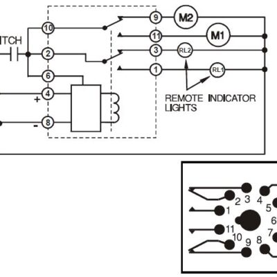
Alternating relay wiring diagram. PDF Time Mark 261 Series Alternating Relay Connect wiring to the socket as indicated in the following examples. The Model 261 series Alternating Relays are extremely versatile and can be used in many other configurations besides those shown. Any type of switch (float, pressure, etc.) can be used as the control switch; however, it must be connected as shown (from L1 to the PDF Schneider Electric Alternating Relay To Match Wiring When Replacing A Hubbell Alternator (Which Uses a SPDT Contact Arrangement) Jumper Pins 13 & 23 On the Schneider Electric Alternator. SCHNEIDER ELECTRIC ALTERNATING RELAY *** When Selecting the Alternating Relay Choose the Model Number Closest to Your Operating Voltage. Coils Can Operate Within a 15% Range. ... › 2020/11/5-pin-relay5 Pin Relay Wiring Diagram - Use Of Relay Nov 05, 2020 · In simple words, a relay is an electromagnetic switch, which we mostly used to switch the power supply automatically or manually. In this post, I am sharing a simple 5 pin relay wiring diagram. Relay is available in different shapes and types. it's can be according to the pins, or contacts, ampers, voltage ratting (AC or DC). Typical Applications for Alternating Relays | Macromatic The Alternating Relay toggles to the LOAD 2 position. The entire cycle is then repeated, but with LOAD 2 energized first. Figure C. DPDT Cross-Wired. In the off state (Figure D), both the LEAD Switch and the LAG Switch are open, the Alternating Relay is in the LOAD 1 position, and both LOAD 1 & LOAD 2 are off. The red LED marked "LOAD 1" is ON.
› ademcoAdemco Vista 20P Wiring Diagram - Home Security Systems ... This option simplifies wiring, and cleans up the panel a bit. Telephone Wiring, Terminals 21-24. Connect the flying leads of an RJ-31X cord to the terminals as shown. The Ademco Vista 20P diagram inside the lid indicates the standard colors for each screw terminal, making things easy. › 2020 › 03What is DOL Starter? Direct Online Starter Wiring and Working Overload Relay: The overload relay has normally connected terminals T1, T2 and T3 that supply power to the motor. The T1 is connected to the point-2 of the contactor. The T2 is connected to the point-4 of the contactor. The T3 is connected to the point-6 of the contactor. Single Phase DOL Starter Wiring Diagram: PDF How To Wire Alternator - Vintage Auto Garage and connect the red wire to the output side of the alternator 10/32 stud, take the long wire and connect to the + side of the coil. If you are using a coil with external ballast resistor connect this wire to the battery side or key switch side of How To Wire Alternator 12-VOLT NEGATIVE GROUND 3 WIRE INSTRUCTIONS Alternating Relay up to 4 loads: Function and Wiring Diagram AVAILABLE AT OUR ONLINE STORE: Alternating Relay is used in special applications where the optimization of ...
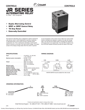
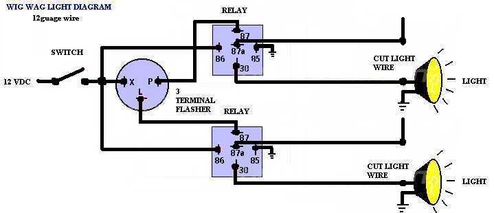
PDF Automation Controls Catalog - crouzet-control.com WIRING DIAGRAM: ORDERING INFORMATION: The electronic alternating relay is designed to replace mechanical style devices used in control applications requiring a duplexing or alternating action of the control circuits to operate pumps, compressors, etc. This is achieved by activating a control switch Wigwag Flashing Lights - Positive Input/Positive Output ... Wigwag Flashing Lights - Positive Input/Positive Output Relay Wiring Diagram. By placing a load on the flasher with a hidden 12V light bulb, power resistor or rheostat, the flasher will cause the coil of the top relay to energize and de-energize and in turn alternate 12V+ to each light for as long as terminal 86 of the bottom relay is connected ... › blog › alternator-voltageAlternator Voltage Regulation 101 (with Wiring Diagrams) - In ... Field or ignition terminal: Allows battery voltage from the ignition to flow to the alternator's field coil during startup. Electronic voltage regulators have been used on many cars since the mid 1970s. 3-Wire Alternator Wiring Diagram. Refer to the diagram below if you're working on three-wire connections. PDF General Purpose, Interposing, Solid-State and Specialty Relays • Magnetic latching relay for energy savings • Dual coil version available Alternating 700-HTA • Alternating feature allows users to select the primary or secondary load or alternate between the two 700-HK700-HK 700-HL 700-HJ700-HJ 700-HG700-HG General Purpose Timing Relays Features 700-HR • Pin-style terminals • Multiple voltage inputs
Alternating Relay, DPDT, 240VAC, 10A, 8 Pin
Relay Wiring Diagram: A Complete Tutorial | EdrawMax The diagram above is the 5 pin relay wiring diagram. There are different kinds of relays for different purposes. It can be used for various switching. Relay can be the best option to control electrical devices automatically. 5 pin is compromised of 3 main pins and an SPDT (single pole double throw).
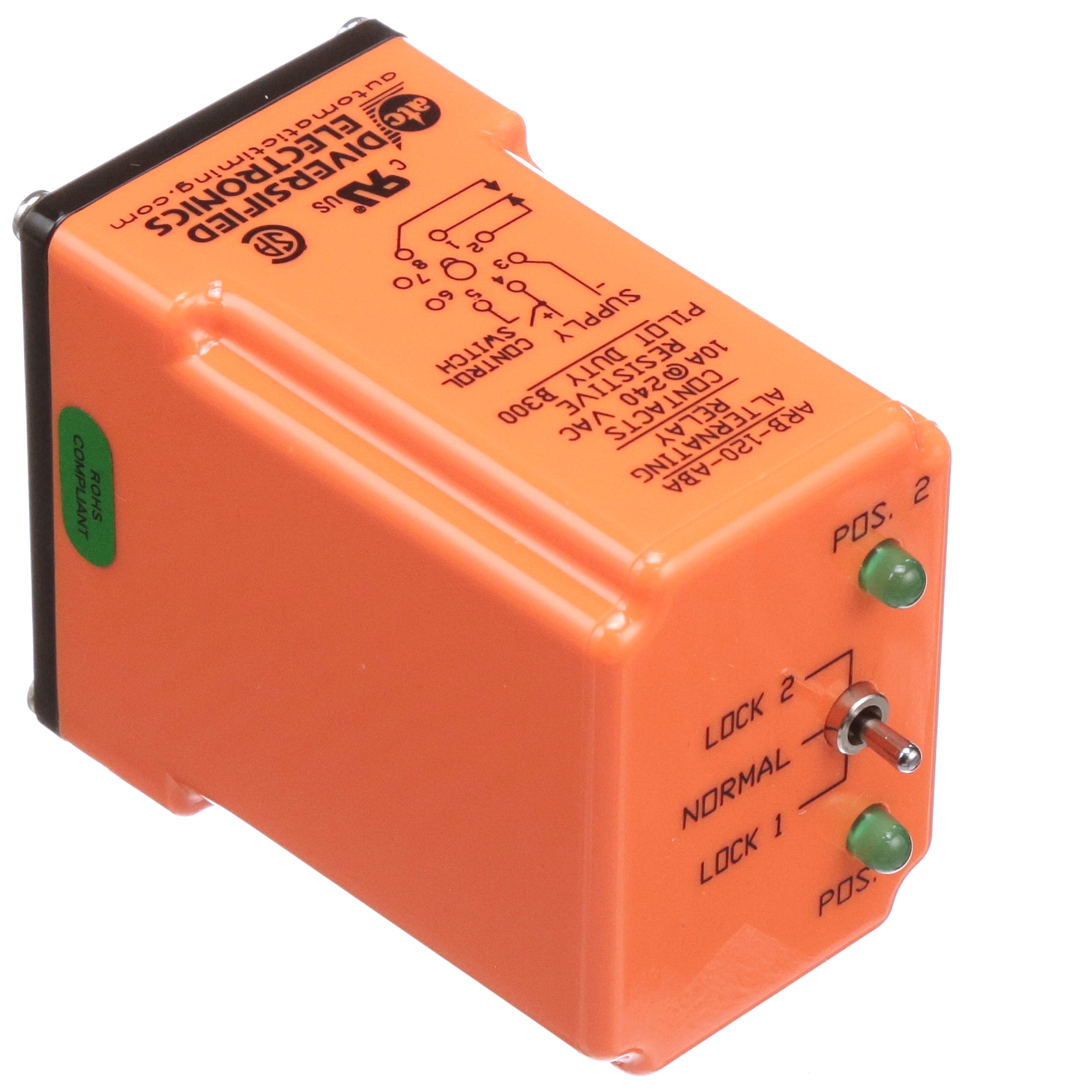
ARB-120-ABA
› peugeot-fault-codesPEUGEOT Fault Codes DTC - Car PDF Manual, Wiring Diagram ... Hello nice to meet you I got problem with my R300 BT (Radio), and need R300 BT wiring diagram for opel astra K 2017 sport tourer to repair it, can you plaeas send the diagram or pins info from R300 BT wiring diagram opel. Thnx ikramidis@hotmail.com #159. Ghaly (Saturday, 12 September 2020 16:36)
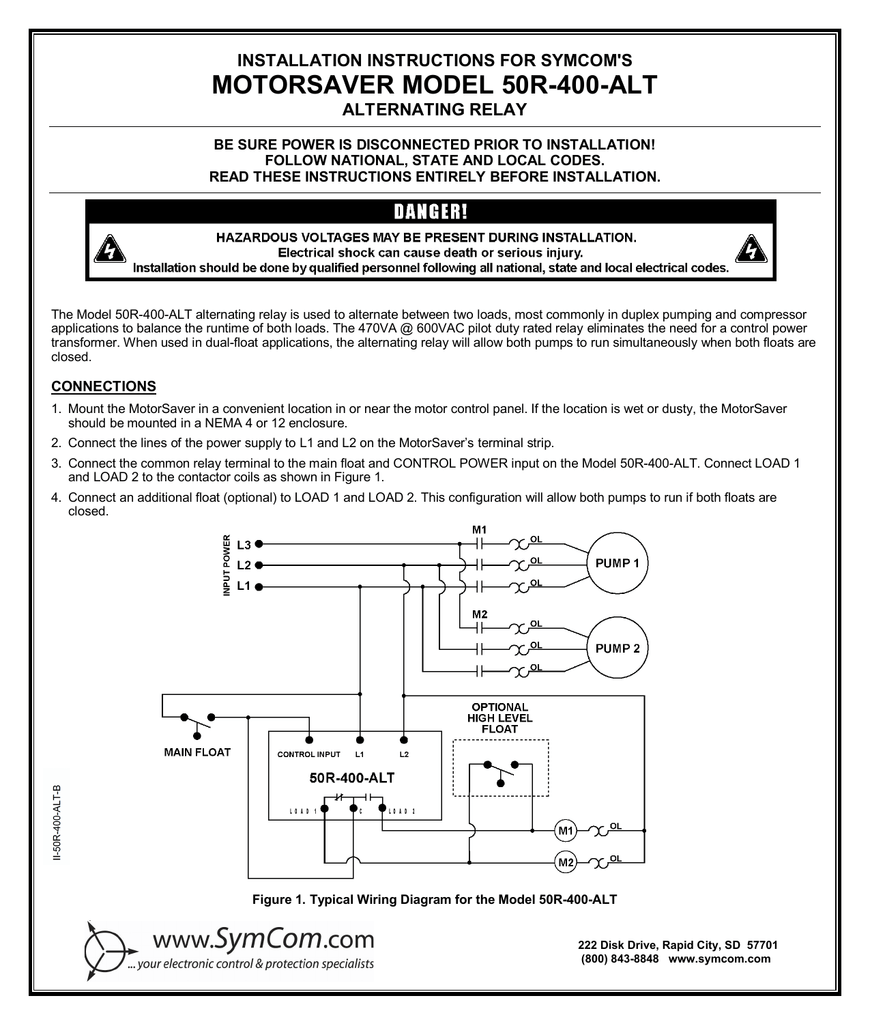
MOTORSAVER MODEL 50R-400-ALT INSTALLATION INSTRUCTIONS FOR ...
PDF MODEL 261 series Alternating Relays - Allied Electronics Connect wiring to the socket as indicated in the following examples. 11 3 The Model 261 series Alternating Relays are extremely versatile and can be used in many other configurations besides those shown. Any type of switch (float, pressure, etc.) can be used as the control switch; however, it must be connected as shown (from L1 to the

ARP120A2R-MCRM
PDF Wiring diagram for starter, alternator - DIY Sprinter Wiring diagram for starter, alternator Code: Designation: Coordinates: K57/4 48 A Battery cutoff relay RHD K88/1 9 L Body manufacturer tml. D+ relay K88/1 18 L Body manufacturer tml. D+ relay K88/1 28 L Body manufacturer tml. D+ relay K88/1 38 L Body manufacturer tml. D+ relay K88/1 50 L Body manufacturer tml. D+ relay N10 6 L SAM control unit ...
Different Types Of Relays, Their Construction, Operation ...
Simple alternator wiring diagram | Alternator, Car ... 35 Awesome ford Starter Relay Wiring Diagram- A run relay is used in the automotive industry to restrict and bend the flow of electricity to various electrical parts inside the automobile. They allow a little circuit to govern a future flow circuit using an electromagnet to govern the flow of electricity inside the circuit.

Typical Applications for Alternating Relays | Macromatic
PDF December 2020, Rev D 901-0000-323 - Macromatic Alternating Relays December 2020, Rev D 901-0000-323 ... terminal numbers on the socket to the ones shown on the appropriate wiring diagram (the wiring diagram on the relay is the view looking towards the bottom of the relay vs. the top of the socket). Plug the relay into the socket, making sure the key on the center post is in the proper

5 Pin Relay Wiring Diagram - Use Of Relay
› relays › relaydiagram8Convert a Negative Output to a Positive Output Relay Wiring ... May 04, 2020 · Convert a Negative Output to a Positive Output Relay Wiring Diagram: If you have a switch or an alarm or keyless entry that has a negative output that you wish to use to switch a device that requires 12V+ such as a horn, dome light, parking lights, head lights, hatch release, etc., wire a relay as shown below to convert the negative output (trigger) to a positive output.
Alternating & Duplexing Relays | Valin
8 Pin Relay Wiring Diagram - Wiring Diagram 8 pin relay wiring diagram - You will want a comprehensive, professional, and easy to know Wiring Diagram. With such an illustrative guide, you'll be capable of troubleshoot, stop, and complete your tasks easily. Not merely will it help you attain your desired results quicker, but also make the complete procedure less difficult for everybody.

Electrical Relay and Solid State Relays for Switching
DAYTON Alternating Relay, 120V AC, 10A @ 240V, 10A @ 28V ... Alternating Relays with DPDT cross-wired outputs are used in applications requiring both (a) the optimization of load usage by equalizing the run time of two loads and (b) additional capacity in case of excess load requirements. ... be used with only one input device—simply wiring the single input device where the "LEAD" input is shown on ...

5 Pin Relay Wiring Diagram - Use Of Relay
Relay and Relay Circuits Schematic Circuit Diagram The overcurrent relays connected to the three phase conductors only control one relay in one phase alternating current circuits and the three phase conductors control the normally closed contact in the control circuit. In the overcurrent relays, the current is set by the adjusting screw on the relay.
Prosense Alternating Relays
PDF 50105 - Painless Wiring attach the black ground wire with one of the mounting bolts. important: the black ground wire must make a good ground or the shutdown relay will not operate properly. note: locating relay forward of or near the front of the engine will help reduce vibration to the relay. 2. remove and discard existing output wire from alternator to battery. 3.
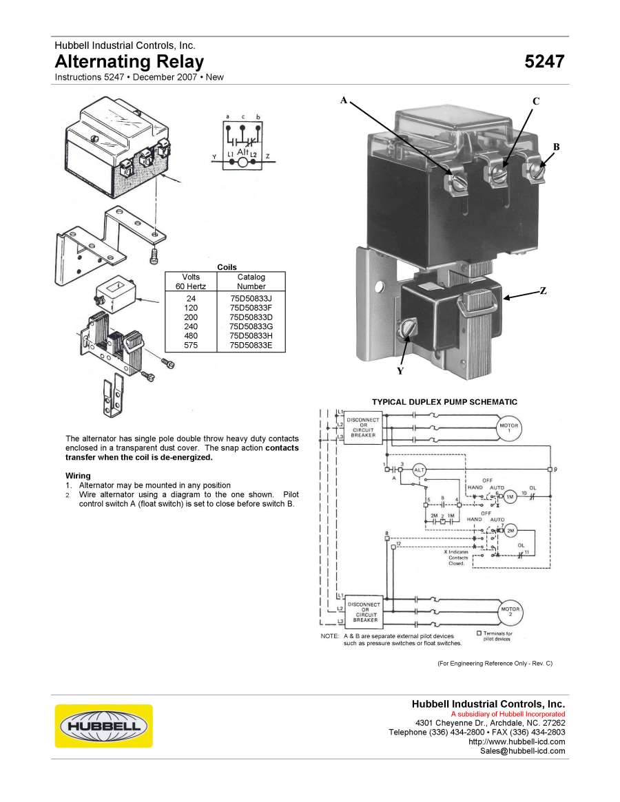
Alternating Relay 5247 Alternating Relay 5247

Macromatic ARP012A3 12V Duplexor Alternating Relay, No Switch

4 Ways to Control Electronic Relays - Make:
Alternating Relay JR | Manualzz
model alt

Alternating Relay circuit Diagram (Explain working principles ...
261-D-12 - TimeMark
HubbellDirect.com: Products: AC-DC Contactors and Relays:5247 ...
261-D-12 - TimeMark

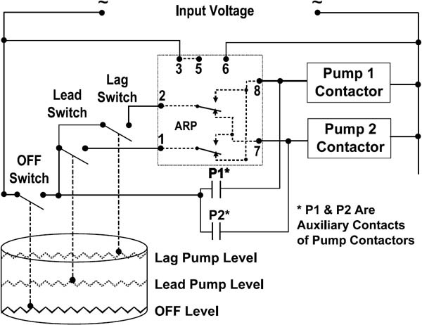
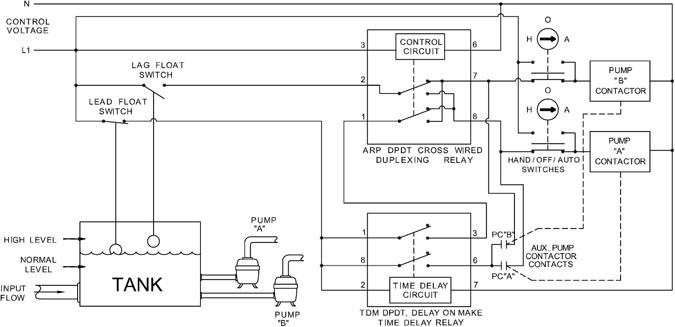
Using DPDT Cross-Wired Alternating Relays with HIGH-LOW Float ...
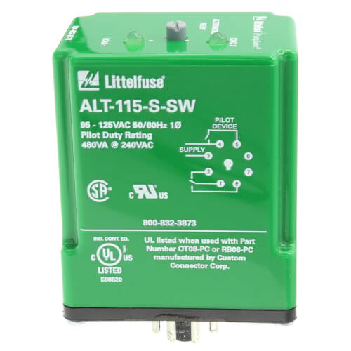
SPDT 8 Pin Plug-In Alternating Relay (95-125V)
HubbellDirect.com: Products: AC-DC Contactors and Relays:5247 ...

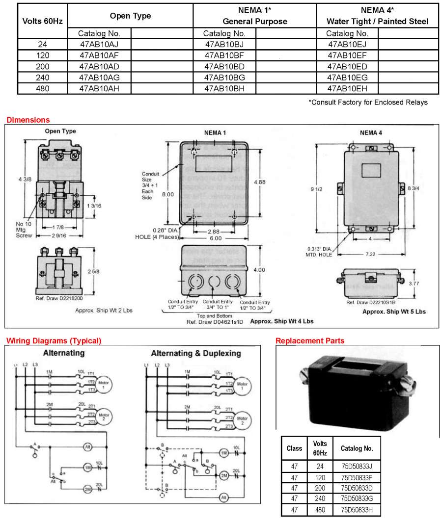
47AB10AF Furnas Alternator
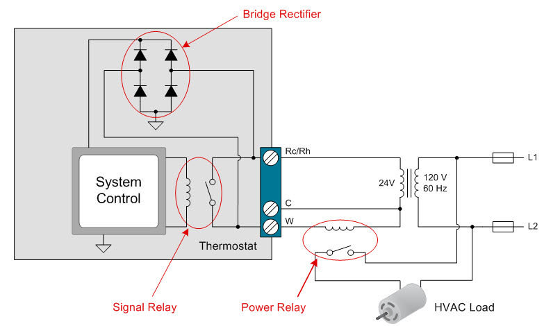
How to power your thermostat using solid state relays ...

261 Alternating Relay from Time Mark

CA2SKE20 - Alternating Relay Wiring | PDF

Wig Wag Alternating Auto Flasher Relay 3 Prong EF30WW

Motor-Control Systems: Relays (part d)
ALT-100-3-SW Alternating Relay
Alternating Relays
Door Locks - 5 Wire Alternating 12 Volts Positive (Type C ...
Protection Relays - ALT SERIES
![DIAGRAM] 240v Airpressor Wiring Diagram FULL Version HD ...](https://i.pinimg.com/originals/b3/38/d7/b338d73b5f79b01f78dc6d2bac449071.jpg)
DIAGRAM] 240v Airpressor Wiring Diagram FULL Version HD ...
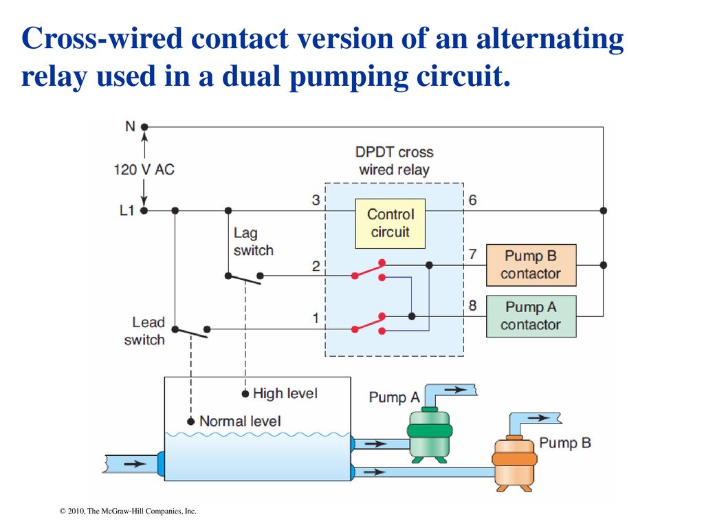
Chapter 7 © 2010, The McGraw-Hill Companies, Inc.. - ppt download
Alternating & Duplexing Relays | Valin

261-DX-12 - TimeMark
Alternating Flasher unit
Electric railway journal . ALL-STEEL PORTABLE SUBSTATION CAR ...
0 Response to "39 alternating relay wiring diagram"
Post a Comment