38 isolated ground receptacle wiring diagram
› manual › 1367779PHILIPS M3001A SERVICE MANUAL Pdf Download | ManualsLib Page 54: Block Diagram Temperature and Invasive Blood Pressure (Temp/Press) measurement Temp Mode Measurement Range: -1 to 45 C (30 to 113 Safety To ensure the safety of the patient, the patient-applied part is isolated from ground by opto- couplers and a transformer. The circuit is also encapsulated in plastic. ελληνοΑγγλικο λεξιλογιο ορων ΒιομηχΑνικης Υγιεινης Cause-effect diagram Διάγραμμα αιτίας- αποτελέσματος ... Composite IBC with plastic inner receptacle Σύνθετο IBC ... Isolated work Απομονωμένη εργασία.242 σελίδες
ΑΦΥΓΡΑΝΤΗΡΑΣ DEHUMIDIFIER Make sure the power cord plug is firmly and securely plugged in. ... Note: The Electric schematic diagram are subject to change without prior notice.68 σελίδες
Isolated ground receptacle wiring diagram
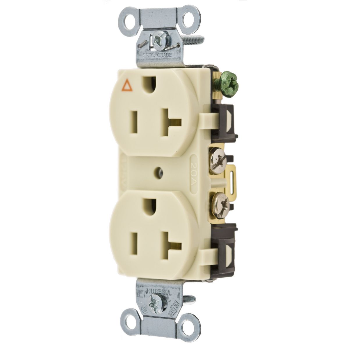
Isolated Ground Receptacle Wiring Diagram - autocardesign Isolated Ground Receptacle Wiring Diagram - wiring diagram is a simplified gratifying pictorial representation of an electrical circuit. It shows the components of the circuit as simplified shapes, and the power and signal connections amid the devices. A wiring diagram usually gives counsel roughly the relative approach and conformity of ... prime plus - User Manual Please isolate the UPS before working according to below diagram. The isolation ... Make sure the protective earth ground wiring is correct. Isolated Ground Heavy Duty Spec Grade Receptacles, Back ... Plastic barrier isolates grounding terminal from mounting strap and metal boxes. Side and internal screw-pressure-plate back wire capability with #14 - #10 AWG copper or copper-clad, solid or stranded wire. Auto-ground clip assures positive ground. For covering patents, see .
Isolated ground receptacle wiring diagram. Isolated Ground Receptacles - The Spruce A basic wiring configuration for an IG receptacle starts with a 3-wire cable with a ground wire. The black hot wire connects to the brass-colored terminal on the receptacle. The white neutral wire connects to the silver-colored terminal, and the bare ground wire connects to the ground screw on the metal electrical box. Isolated ground panel wiring diagram An isolated ground (IG) is a local ground connection used with a supply, one of the common earthing arrangements used with domestic mains supplies. Receptacle wiring diagram examples ground fault receptacle wiring. Normally, this current is shunted around the patient via the ground conductor in the . Mike Holt Enterprises offers comprehensive. Hospital Grade Receptacle Wiring Diagram - U Wiring Hospital Grade Receptacle Wiring Diagram Author. Isolated ground premium hospital grade receptacles rating a vac nema description color suffix catalog no. One individual recently indicated that the medical buildings patient-care areas are being wired using hospital MC cable. That picture Hospital Grade Receptacle Wiring Diagram in. › wiring_ecuMotorsports ECU Wiring Harness Construction Wiring thermocouples into a motorsport harness is a bit different than industrial applications as we typically use a a three position plug / receptacle connection in a branch off the harness. If the thermocouple is shielded then one terminal of the three position connector should connect the shield/drain from the main harness to the thermocouple.
isolated ground receptacles are identified by - DH-NX ... isolated ground receptacles are identified by - Diagram Schematic. The isolated ground jade learning 517 16 use of receptacles how is an receptacle identified quora on vimeo code quandaries ec m leviton lev lok 15a and 20a 125v electrical business heavy duty decorator hospital grade back side wire white commercial outlets wiring devices bryant 20 a orange no tamper resistant 52he34 sp83igoa ... How do I install an isolated ground circuit ... The isolated ground is a separate, _insulated_ equipment grounding conductor that goes right back to the main ground bus, with no connections to other bonded metal. An isolated ground provides for the benefits of star single point equipment grounding in an environment with multiply connected equipment grounding paths. IG wiring on direct connected circuits — As per 250.96(B), Isolated Grounding Circuits, "Where required for the reduction of electrical noise (electromagnetic interference) on the grounding circuit, an equipment enclosure supplied by a branch circuit shall be permitted to be isolated from a raceway containing circuits supplying only that equipment by one or more listed nonmetallic raceway fittings located at the point of attachment of the raceway to the equipment enclosure. The metal ... Isolated Grounding Receptacle Circuits - Got Clean Grounds ... Isolated ground receptacles are intended to be used for reduction of electromagnetic interferences as previously reviewed in this article. These receptacles have a grounding terminal that is purposely insulated for connection to the isolated equipment grounding conductor of the branch circuit when installed in an outlet box.
tc.canada.ca › en › marine-transportationShips Electrical Standards (2018) - TP 127 E 11.38 The wiring between the indicator panel and the watertight duplex receptacle at the side, masthead, anchor and stern lights shall be in duplicate and may be either two, 2-conductor cables or one 4-conductor cable. PDF Isolated Ground Receptacle Wiring Diagram isolated gnd bus equipment gnd bus ground bus neutral bus 208/120v bus neutral l n iso. gnd ground (equipment) enclosure ig receptacle (if used) main breaker receptacle panel no scale receptacle wiring diagram isolated ground 26052602.dgn Mike Holt Isolated Ground - Computer Power (8-3-99) The new and empty neutral bus will need to be labeled "Isolated Ground" and connected to the PDU ground with appropriately sized wire for the service. Then you connect the phase conductors to the breakers, the white to the neutral buss bar, the ground from the conduit and boxes to the "Equipment Grounding Conductor", and the last, isolated ground to the "Isolated Ground". Isolated Ground Wiring Diagram Receptacle - DALEACA Ef32 Isolated Ground Receptacle Wiring Diagram Epanel . Grounding . Ground Wiring Diagram . Pass Seymour Electrical Wiring Devices 2017 2018 . Nec 2017 Code Changes Update . Leviton 5662 Ig 15 Amp 250 Volt Nema 6 15r 2p 3w Slim . Diagram Roketa Mc 54b Wiring Diagram Full Version Hd . Lightning Surge Protection And Earthing Of Electrical . Pass ...
The Basics of Isolated Grounding Receptacles. Oct. 1, 2001. An isolated ground receptacle (IGR) can reduce electrical noise, but if installed incorrectly, it can create a dangerous installation. This receptacle differs in construction from its self-grounding counterpart. The grounding terminal for an IGR is insulated from its metal mounting yoke.
Isolated Ground Wiring Diagram - magnifico Gnd ground equipment enclosure ig receptacle if used main breaker receptacle panel no scale receptacle wiring diagram isolated ground 26052602dgn. House Circuit Breaker Wiring Diagram-EET-2021. A basic diagram of this type of improper wiring can be seen below where a separately driven ground rod is used to reference the insulated equipment ...
The Facts and Myths of Isolated Grounding - Part 1 | iGround A basic diagram of this type of improper wiring can be seen below, where a separately driven ground rod is used to reference the insulated equipment grounding bus in a sub-panel. In 1984, responding to this and other incidents, the authors of the National Electrical Code provided installation requirements for an isolated equipment grounding conductor.
Isolated Ground Receptacle Wiring Diagram - ZYNRA-ZINXIE Isolated Ground Receptacle Wiring Diagram Oleh Anonim Juli 06, 2020 Posting Komentar Installing Basic Wiring Outlets Diagrams Schematics Online . Diagram 3 5mm Isolated Gound Wiring Diagram Full Version Hd . China Tamper Resistant Isolated Ground Duplex Receptacle .
Isolated Ground Transformer Wiring Diagram - U Wiring 3 phase isolation transformer wiring diagram Low Voltage Transformer Wiring Diagram New Nih Standard Cad Details E isolated Ground. Isolated ground transformer wiring diagram. Gnd ground equipment enclosure ig receptacle if used main breaker receptacle panel no scale receptacle wiring diagram isolated ground.
DeWALT Wiring Diagrams Professional Pocket Reference Isolated Ground Receptacle GFCI Split-Wired GFCI Wiring Diagrams Wiring Diagrams for NEMA Configurations Wiring Diagrams for Switches Wiring Diagram of Split-Wired Receptacles and Switched Circuit Single Pole Switch Circuit Single Pole Operating a Light with Additional Independent Receptacle Double-Gang Switch - Each Controls a Light
isolated ground circuit diagram - DH-NX Wiring Diagram isolated ground circuit diagram - Diagram Schematic. Isolated ground on vimeo the factyths of grounding part 1 iground jade learning ecn electrical forums 31 common household circuit wirings you can use for your home 2 how to eliminate loops with signal isolation projects receptacles liebert web breaking functional reduce data transmission errors analog devices 517 16 26052602 receptacle ...
9.3 Electrical - Architecture Engineering and Construction 26052602 - Isolated Ground Receptacle Wiring Diagram-alt: March 2014: PDF: Microstation: AutoCAD: 26052603 - Transformer Pad Grounding Detail-alt: March 2014: PDF: ... 26200001 - Service Entrance Transformer Wiring Diagram: April 2014: PDF: Microstation: AutoCAD: 26200002 - Step Down Transformer Wiring Diagram: August 2020: PDF:
Isolated Ground on Vimeo A brief overview of how an isolated ground outlet is wired, compared to a standard outlet. Diagram is from Middle Atlantic's power and grounding white paper.…
Isolated Ground Receptacle Wiring Diagram ... Isolated Ground Receptacle Wiring Diagram Oleh Anonim Juni 29, 2020 Posting Komentar Installing Basic Wiring Outlets Diagrams Schematics Online . Diagram 3 5mm Isolated Gound Wiring Diagram Full Version Hd . China Tamper Resistant Isolated Ground Duplex Receptacle .
Circuit Breaker Wiring Diagrams - Do-it-yourself-help.com Wiring for a 15 Amp Isolated Ground Circuit. An isolated-ground receptacle makes use of an extra wire to provide a separate, dedicated ground in the circuit. In a 15 amp circuit, the red wire in a 14/3 cable is used for this purpose and marked green at both ends.
Isolated Ground | Receptacles, Wire, Outlet wiring Sep 20, 2016 - A brief overview of how an isolated ground outlet is wired, compared to a standard outlet. Diagram is from Middle Atlantic's power and grounding white paper.… Pinterest
Isolated Ground Receptacle Wiring Diagram : Isolated ... Isolated Ground Receptacle Wiring Diagram : Isolated Ground Duplex Receptacle Outlet Heavy Duty Industrial Specif Leviton - Robert Smith Jumat, 17 Desember 2021 This doesn't turn an ungrounded outlet into a grounded outlet, but it does provide protection against shock.
› manual › 1410873DAIKIN DPS005 INSTALLATION AND MAINTENANCE ... - ManualsLib To receptacle is provided in the main control box on all units. The use this receptacle, connect a separate field-supplied 115 V receptacle shall be powered by a factory installed and wired power wiring circuit to the outlet. Page 78: Wiring Diagrams
Duplex Receptacle Wiring Diagram - The Wiring Wiring diagram for a 20 amp 120 volt duplex receptacle a 20 amp 120v duplex receptacle outlet like this should be installed in a circuit using 12 awg cable and a 20 amp circuit breaker. Wiring diagram duplex pump control schematic isolated ground wiring understanding the differences between bonding grounding and 3 wire cord diagram wiring ...
Isolated Ground Wiring Diagram Receptacle ... Ef32 Isolated Ground Receptacle Wiring Diagram Epanel . Grounding . Ground Wiring Diagram . Pass Seymour Electrical Wiring Devices 2017 2018 . Nec 2017 Code Changes Update . Leviton 5662 Ig 15 Amp 250 Volt Nema 6 15r 2p 3w Slim . Diagram Roketa Mc 54b Wiring Diagram Full Version Hd . Lightning Surge Protection And Earthing Of Electrical . Pass ...
PDF Industrial Grade ed! Isolated Ground GFCI Duplex Receptacles Description Industrial Grade Isolated Ground Duplex Receptacles AC Horsepower Rating At Rated Voltage 1 HP Electrical Specifications Amperage 15A or 20A Voltage 125VAC NEMA 5-15R or 5-20R Grounding Isolated ground Pole 2 Wire 3 Dieelectric Voltage Withstands 1250VAC per UL 943 and CSA-C22.2 No. 144.1-06 Short Circuit Current Rating 10kA
Isolated Ground Heavy Duty Spec Grade Receptacles, Back ... Plastic barrier isolates grounding terminal from mounting strap and metal boxes. Side and internal screw-pressure-plate back wire capability with #14 - #10 AWG copper or copper-clad, solid or stranded wire. Auto-ground clip assures positive ground. For covering patents, see .
prime plus - User Manual Please isolate the UPS before working according to below diagram. The isolation ... Make sure the protective earth ground wiring is correct.
Isolated Ground Receptacle Wiring Diagram - autocardesign Isolated Ground Receptacle Wiring Diagram - wiring diagram is a simplified gratifying pictorial representation of an electrical circuit. It shows the components of the circuit as simplified shapes, and the power and signal connections amid the devices. A wiring diagram usually gives counsel roughly the relative approach and conformity of ...

0 Response to "38 isolated ground receptacle wiring diagram"
Post a Comment