42 gamecube controller circuit board diagram
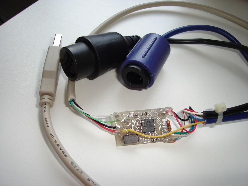
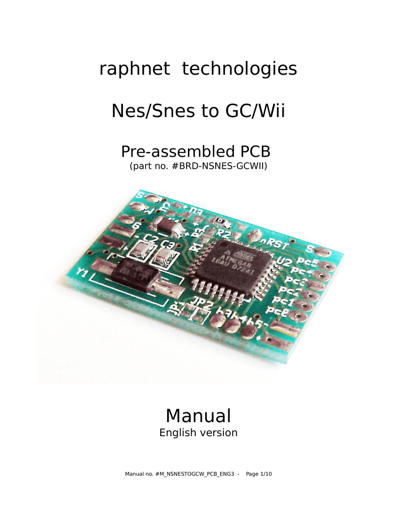
The PCB's structure can be regarded as simple nodes (like solder and button points) and connections (paths) between those nodes (this is how electronics diagrams are made). Because electricity travels near the speed of light, as long as they connect, the length of the paths between nodes is not really important. Printed Circuit Board Top The PCB is an improved version of the PCB used for the Nes/Snes controller to USB.. This new PCB has a voltage regulator and reprogramming contacts on the bottom side. Here are composite images of the top and bottom layers: Bottom
Dec 08, 2017 · Question Gamecube Controller Bare Minimum For Function Bitbuilt Giving Life To Old Consoles. Gamecube controller pinout issue 4 looping a signal with wires project bluetooth mod kit guide breakout box external arduino nes snes n64 to pcb homepage mbed wii raphnet 1st party diy wireless usb adapter ports microcontroller nintendo 64 for bare minimum wiring diagram connect switch mario png indigo ...
Gamecube controller circuit board diagram
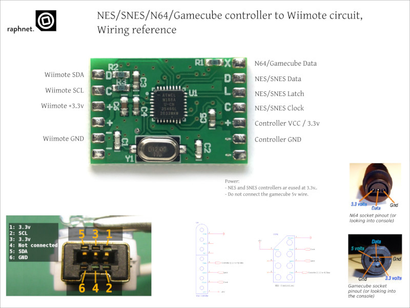
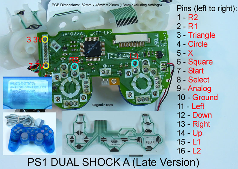
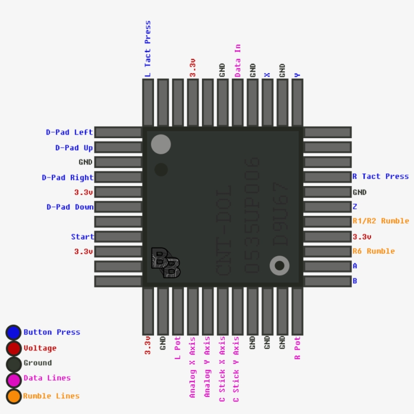
G Gamecube 5 volt This is the board's 5 volt output H Gamecube 3.3 volt This is the board's 3.3 volt output (pass through) I Gamecube Gnd Ground J Gamecube Data Communication with the gamecube controller N64 pinout reference Gamecube pinout reference of the wire colors in the cable. Do NOT try to follow this Buttons like that are open circuit when not pressed, leave it open circuit for the time being. It's likely to be for enabling some feature, Line 12 does appear to be initialising the input pin so it should correspond to pin 4 in the diagram. The ground goes to both the ground pin on the red board and the ground of the controller. Once you know which wire does what in your cable, solder them to the appropriate locations on the PCB: IMPORANT: Solder the Gamecube data wire to the location ...
Gamecube controller circuit board diagram. Here are a number of highest rated Printed Circuit Board Schematics pictures upon internet. We identified it from reliable source. Its submitted by presidency in the best field. We say yes this nice of Printed Circuit Board Schematics graphic could possibly be the most trending subject when we allocation it in google improvement or facebook. I know for one thing, you can strip apart a Gravis USB pad and solder the contact buttons from the Gamecube pad to that and use the Gravis pad as a connection to USB. but that would use up a perfect fine Gravis pad and would be too much slutter with the wires and junk. dothedre, May 6, 2006 #4 (You must log in or sign up to reply here.) Here's how it will work: - The joystick uses two potentiometers (X and Y axis). - Each axis will have four arcade buttons assigned to it (one high, one low, and two modifiers). - Four buttons are arranged in the WASD formation like how you move in computer games. Printed Circuit Board Multiuse Pcb2. Save Image. Nt 3540 Controller Diagram Additionally Gamecube Controller Wiring Diagram Free Diagram. Save Image. Diagram Of Gamecube Joystick Pcb The Official Modretro Forums. Save Image. Wavebird Inside A Wired Controller Youtube.
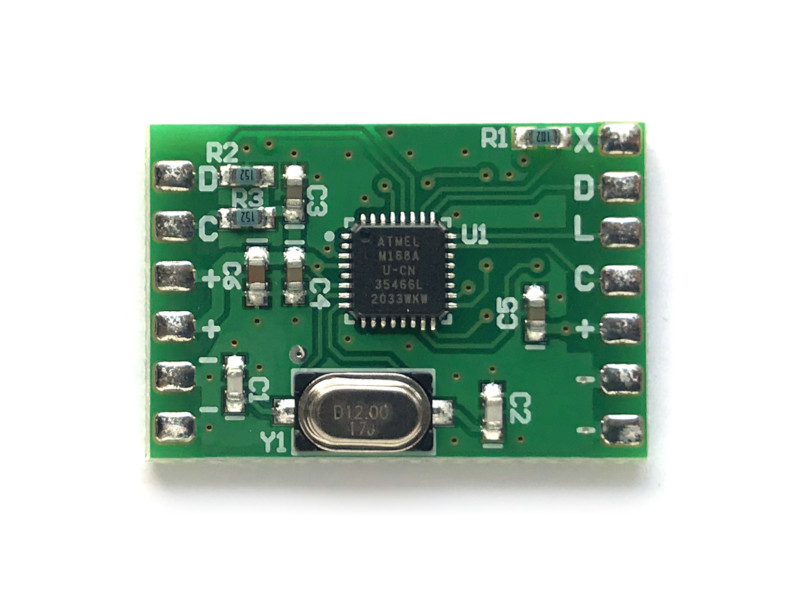
I have the pleasure of taking a CAD/3D Printing class is my school, I was wondering if I could find in depth dimensions for the gamecube controller… Nintendo GameCube Bit Tool Phillips #1 Screwdriver Phillips #2 Screwdriver Parts No parts specified. Step 1 Top Case Turn over the Gamecube so that the bottom side is facing up. Locate the four screws (circled in red) on each corner of the device. Then, use a 4.5 mm Gamebit screwdriver to remove all four screws. Add a comment Step 2 The circuit board connects all the components within the controller and provides structural support for buttons, sticks, and chips. Tools Buy these tools Tri-point Y0 Screwdriver $5.49 Buy Tweezers $4.99 Buy Parts No parts specified. Step 1 Back Panel Place the controller (buttons down) on a solid surface. Description This circuit makes it possible to use a NES, SNES, N64 or Gamecube controller on a Wii or Wii-U by connecting to the wiimote as a classic controller. Ideal for Wii virtual console games on systems without gamecube ports. Features: Supports N64 controllers (Official and most 3rd party, including the Hori Mini)
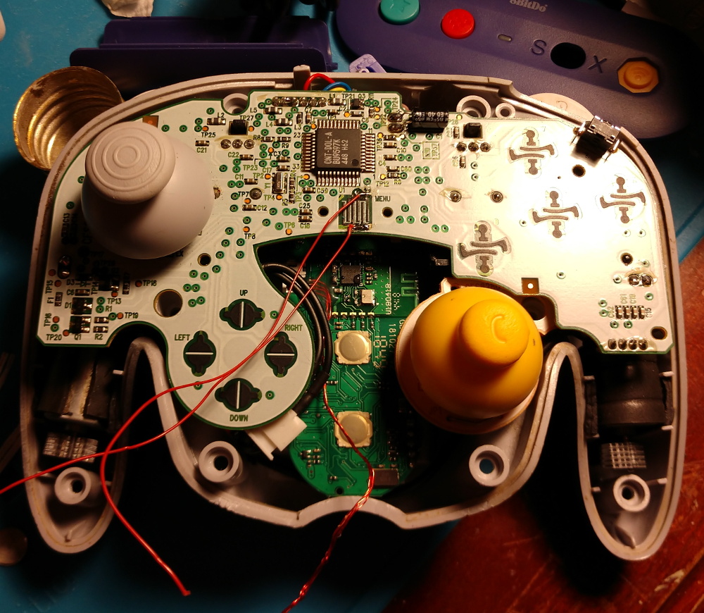
After soldering in the battery and data lines from the controller, the ESP32 communicates with the GameCube controller, requesting button reports. The device runs as an Bluetooth Joystick, which can connect to and control a variety of devices. All code and board files have been posted. Heres some demos of Switch as well as Mac/PC support. TurboGrafx-16 Schematic 1 - Hu6280 Circuit TurboGrafx-16 Schematic 2 - Hu6270 Circuit TurboGrafx-16 Schematic 3 - Hu6260 Circuit TurboGrafx-16 Schematic 4 - Power Input PC Engine Chip Pinouts PC Engine Socketed HuCard PWD-653 Nintendo Game Boy Game Boy Schematic - CPU Game Boy Schematic - LCD Game Boy Schematic - Memory Game Boy Schematic - Power Nintendo Gamecube Controller Protocol. ... Some home made hardware (circuit diagram to follow shortly, but there is a description of pin connections in the source code for the impatient or the hardcore, which should be just enough to be able to build it). The giveio ... 1. Start by carefully planning how you will install the circuit inside the controller (or your enclosure). Make sure you dont cut the wires too short and that the circuit will not be in the way when you put back the cover. 2. Select controller type (see section 3) 3. Solder the Gamecube wires (see section 4) 4. Solder the NES and SNES wires (see section 4)
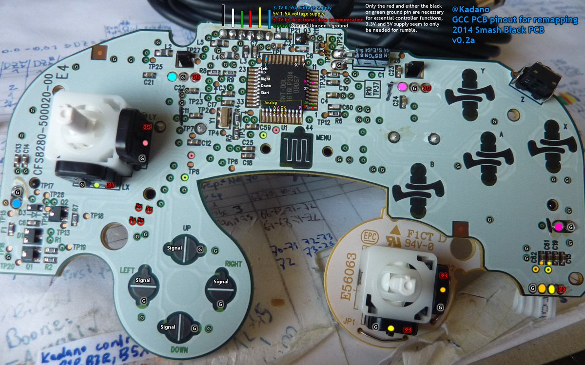
Kadano on Twitter: "Gamecube controller PCB pinout ...
The GameCube controller is the standard game controller for the GameCube home video game console, manufactured by Nintendo and launched in 2001. As the successor to the Nintendo 64 controller, it is the progression of Nintendo's controller design in numerous ways.The contentious M-shaped design of its predecessor was replaced with a more conventional handlebar style controller shape; a second ...

GameCube Controller Internals Guide – The GCC Library
Requirement: The buttons, printed circuit board, joysticks, and housing for the BIU must be no larger than the size of a standard GameCube controller. 2.3 Microcontroller Unit The Microcontroller Unit (MCU) is the main brains of the MacroME controller. It receives all inputs from the BIU, and outputs the remapped buttons or macros to the game ...

GameCube Controller Internals Guide – The GCC Library
Repair... Nintendo GameCube Controller troubleshooting, repair, and service manuals. ... Nintendo GameCube Controller Circuit Board Replacement.

GameCube controller pcb broken, fixable ? : r/consolerepair
Game Console RGB SCART Cable Diagrams. For anyone unfamiliar with what RGB video is see this Video Primer. SCART pinouts and signal info can be found here.. SCART (aka Peritel or Euroconnector) cables for home video game consoles aren't standard, they are different for each console.
minGC Controller Board - gc-forever - Gamecube/Wii Forums
The GameCube controller is a favorite among the console ... The design of the circuit board is just under a square inch and includes connections ... and ground coming from the controller board.

Fix Any Video Game Controller : 9 Steps (with Pictures ...
GameCube Controller Internals Guide. The GameCube controller saw two major redesigns of its internals. They are denoted as T1, T2, and T3, which mainly represents the different stick mechanisms, or stickboxes, as it’s the most important component of the controller. I will also document the different internals, and point out small differences ...
N64/Gamecube controller to USB adapter
GameCube controller: Analyze the protocol used to communicate with the GameCube game system. These signals will be translated to equivalent Nintendo 64 signals. The GameCube controller, shown in Figure 7, has 6 discrete digital buttons, 2 analog slider pads with a digital button, a directional pad, and 2 analog joysticks.

GameCube Controller Main Circuit Board / PCB - Genuine Nintendo Part | eBay
Nes Circuit Board. Here are a number of highest rated Nes Circuit Board pictures upon internet. We identified it from honorable source. Its submitted by running in the best field. We say you will this nice of Nes Circuit Board graphic could possibly be the most trending subject later we allowance it in google lead or facebook.
raphnet. - NES/SNES/N64/Gamecube controller to Wiimote circuit
Bennie Glassnere Bennie Glassnere Volkswagen Jetta S 2012 Fuse Diagram For the Volkswagen CC 2008, 2009, 2010, 2011, 2012,… Read more December 23, 2021 Post a Comment High Yield Psychiatry Pdf Free Download How to Export a File as a PDF … Read more December 03, 2021 Post a Comment Encyclopedia Of Hell Pdf Free Download
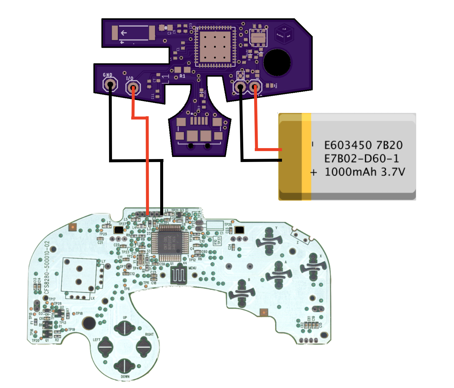
Project | BlueCubeMod: Bluetooth GameCube Controller Mod Kit ...
The smallest time unit in the gamecube controller protocol is of 1us, which corresponds to only 16 cpu cycles at 16 mhz. Not much time to waste at that speed.

GameStop GS3 GameCube Controller Motherboard Replacement ...
Figure 1: Layout of a standard Nintendo GameCube Controller Figure 1 shows the standard design of a GameCube controller [8]. MacroME will utilize a standard GameCube controller shell, and as such will look very similar to existing official and third-party controllers. However, there will be extra buttons for macros, as well as

GameCube Controller Teardown – Making Studio
26 Feb 2017 — Gamecube controller PCB pinout / documentation: ... way better than any other diagrams out there, thanks!

Are Third Party Gamecube Controller Parts Compatible with Nintendo's?
Here it is. Connect all the spots where the exposed metal on the controller port one went into the controller circuit board. Then connect that mass of wires to the bundle of exposed wires on the outside, and in the middle of the controller wire. Remember, this diagram is when looking at the GC controller port one, from the front.

Official Gamecube controller mapped traces and pins | The ...
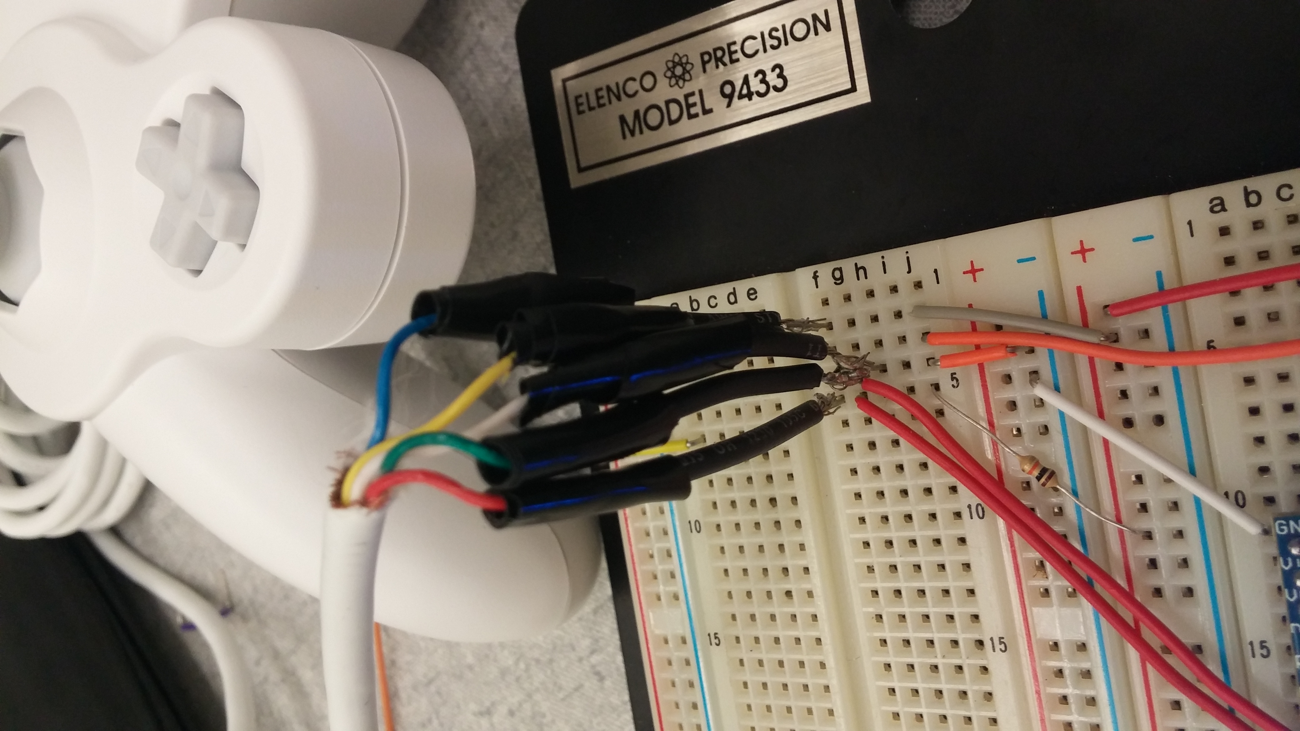
Once you know which wire does what in your cable, solder them to the appropriate locations on the PCB: IMPORANT: Solder the Gamecube data wire to the location ...
GameCube controller - Wikipedia
Buttons like that are open circuit when not pressed, leave it open circuit for the time being. It's likely to be for enabling some feature, Line 12 does appear to be initialising the input pin so it should correspond to pin 4 in the diagram. The ground goes to both the ground pin on the red board and the ground of the controller.

PCBMay is a professional controller PCB boards manufacturer ...
G Gamecube 5 volt This is the board's 5 volt output H Gamecube 3.3 volt This is the board's 3.3 volt output (pass through) I Gamecube Gnd Ground J Gamecube Data Communication with the gamecube controller N64 pinout reference Gamecube pinout reference of the wire colors in the cable. Do NOT try to follow this
Joystick Controller - PCB and Wiring
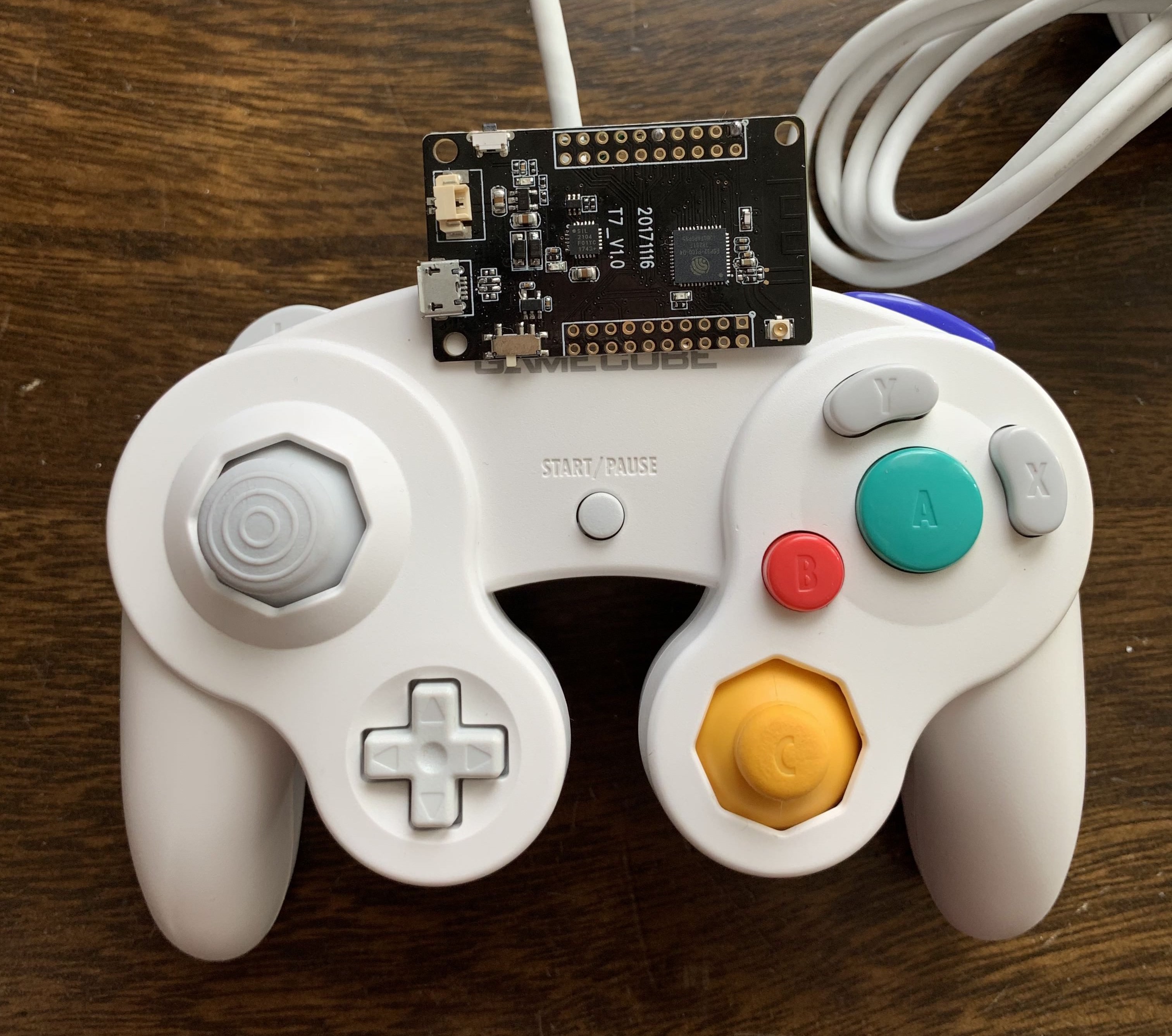
Make your own BlueCubeMod, added firmware & PCB files ...

GameCube Controller Internals Guide – The GCC Library
Wavebird Rumble Mod? - Page 1 - gc-forever - Gamecube/Wii Forums

Projects: A better gamecube controller? (Part 2: Electrical ...
WaveBird | Hackaday
1st Party Gamecube Controller Pinout - Gc Controller Pinout ...

GameCube Controller Internals Guide – The GCC Library

Nintendo GameCube Controller Circuit Board Replacement ...
Homepage - | Mbed

gamecube controller pcb traces - Album on Imgur
Question - GameCube Controller Bare Minimum for Function ...

GameCube Architecture | A Practical Analysis

Is this circuit salvageable? I pulled this from a Nintendo's ...
MacroME: The Programmable GameCube Controller

Nintendo GameCube Controller (Official) Teardown - iFixit

Fix Any Video Game Controller : 9 Steps (with Pictures ...

Nintendo Controller Teardown - Part 1 - Fictiv
Board scan - Wavebird Board Scans and Documentation ...
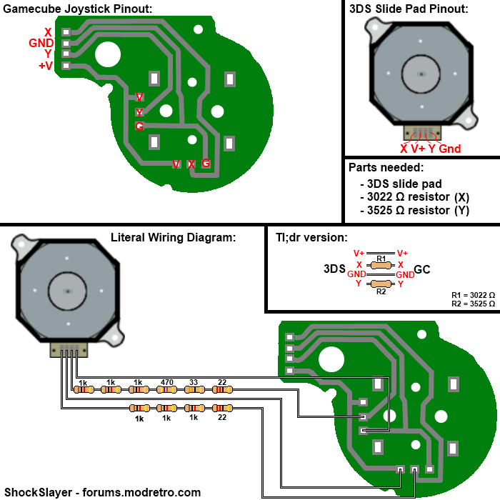
Diagram of gamecube joystick PCB | The Official ModRetro Forums
raphnet. - NES/SNES/N64/Gamecube controller to Wiimote circuit

FIRES SLICKbox — FIRES Custom Controller
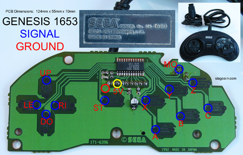
pin #5 on gen pad for 5Volts, question;
N64 to Gc/Wii PCB - User`s manual | 4.4) PCB wiring diagram

GameCube Controller Pinout · Issue #4 · lastxserenade/info ...

Projects - Nintendo Wii Portable | Project G-Wii Australia
0 Response to "42 gamecube controller circuit board diagram"
Post a Comment