in the diagram, curves 1, 2, and 3 represent
Free 4 Step Simple Diagram for PowerPoint is a creative diagram design containing four components that can be used to represent a concept or idea while presenting a topic in PowerPoint. This free four stages diagram for PowerPoint can be used in a wide range of business PowerPoint presentations. There are, in fact, an infinite number of other points on the isoquant Q 1 all of which represent different combinations of K and L which can be used to produce Q 1 units. Output Q 2 and Q 3 can be produced using any of the combinations of K and L represented by points along the isoquants.
In the diagram curves 1,2,3 represent. total fixed cost, total variable cost, and total cost respectively. If a firm wanted to know how much it would save by producing one less unit of output, it would look to: MC.

In the diagram, curves 1, 2, and 3 represent
A Venn diagram is a widely used diagram style that shows the logical relation between sets, popularized by John Venn in the 1880s. The diagrams are used to teach elementary set theory, and to illustrate simple set relationships in probability, logic, statistics, linguistics and computer science.A Venn diagram uses simple closed curves drawn on a plane to represent sets. These curves represent the relationships between phase-transition temperatures and pressures. The point of intersection of all three curves represents the substance's triple point—the temperature and pressure at which all three phases are in equilibrium. In the diagram, curves 1, 2, and 3 represent: a. average variable cost, marginal cost, and average fixed cost respectively. b. total variable cost, total fixed cost, and total cost respectively. c. total fixed cost, total variable cost, and total cost respectively. d. marginal product, average variable cost, and average total cost respectively.
In the diagram, curves 1, 2, and 3 represent. In the diagram, curves 1, 2, and 3 represent the: marginal, average, and total product curves respectively. In the figure, curves 1, 2, 3, and 4 represent the: MC, ATC, AVC, and AFC curves respectively. The diagram suggests that: when marginal product lies above average product, average product is rising. [Solved] In the diagram, curves 1, 2, and 3 represent the A)average, marginal, and total product curves respectively. B)marginal, average, and total product curves respectively. C)total, average, and marginal product curves respectively. D)total, marginal, and average product curves respectively. In the above diagram curves 1, 2, and 3 represent the: A. average, marginal, and total product curves respectively. B. marginal, average, and total product curves respectively. C. total, average, and marginal product curves respectively. D. total, marginal, and average product curves respectively. A Venn diagram must contain all 2 n logically possible zones of overlap between its n curves, representing all combinations of inclusion/exclusion of its constituent sets. Regions not part of the set are indicated by coloring them black, in contrast to Euler diagrams, where membership in the set is indicated by overlap as well as color. When the number of sets grows beyond 3 a Venn …
3 3D Space In order to represent points in space, we first choose a fixed point O (the origin) and three directed lines through O that are perpendicular to each other, called the coordinate axes and labeled the x-axis, y-axis, and z-axis. Usually we think of the A curve drawn in a graph represents a function, if every vertical line intersects the curve in at most one point. Question 1 : Determine whether the graph given below represent functions. (a) Using a scale of 1 cm to represent 1 hour, draw a horizontal x-axis for 0 ≤ x ≤ 9. Using a scale of 2 cm to represent 1 °C, draw a vertical y-axis for 02 ≤ y ≤ 4. On your axes, plot the points given in the table and join them with a smooth curve.[3] (b) Use your graph to find an estimate for (i) the temperature when x #5.5, [1] In the above diagram curves 1, 2, and 3 represent the: A) average, marginal, and total product curves respectively. B) marginal, average, and total product curves respectively. C) total, average, and marginal product curves respectively. D) total, marginal, and average product curves respectively. Answer: B
In the above diagram curves 1, 2, and 3 represent the: A. average, marginal, and total product curves respectively. B. marginal, average, and total product curves respectively . C. total, average, Just from $13/Page. Order Essay . Continue to order Get a quote. Post navigation. Venn Diagram For 2 Sets. Venn Diagram for 2 Sets i.e. n ( A ∪B) = n (A) + n (B) - n ( A ∩ B) is shown below: In the above Venn Diagram, A represents the Number of elements belonging to Set A only. B represents the Number of elements that belong to Set B only. A & B represent the Number of elements that belong to both Sets A and B. Transcribed image text: In the diagram below curves 1, 2, and 3 represent the: Q2 Curve 1 Q1 What are these curves? LI L2 LE Labor ???? TERRE Curve 2 Curve 3 Labor L2 LG A. average, marginal, and total product curves respectively. B. total, average, and marginal product curves respectively. C. marginal, average, and total product curves respectively. A Venn diagram is used to visually represent the differences and the similarities between two concepts. Venn diagrams are also called logic or set diagrams and are widely used in set theory, logic, mathematics, businesses, teaching, computer science, and statistics. Let's learn about Venn diagrams, their definition, symbols, and types with solved examples. 1. What is a Venn …
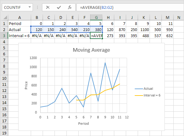
Moving Average in Excel - Easy Excel Tutorial
This 2-slide Accomplishments Diagram for PowerPoint has flat design high resolution vector shapes and icons. It is an editable template for PowerPoint and change in size of images does not effects the picture quality of Presentation. The first slide shows a 5-step diagram in a half circle shape with trophy image in the middle. The trophy is a ...

The full curve is equation (3): q(X)/Q 0 = 1 − exp X Erf X ...
As far as I understand, electricity should be able to flow in the diagrams 1, 2 and 4. Is this correct or am I missing something? https://imgur.com/gallery/RgzyR5Y

Maxwell-Boltzmann probability density function ...
Output In the diagram, curves 1, 2, and 3 represent: total variable cost, total fixed cost, and total cost respectively. average variable cost, marginal cost, and average fixed cost respectively. O marginal product, average variable cost, and average total cost respectively. total fixed cost, total variable cost, and total cost respectively.
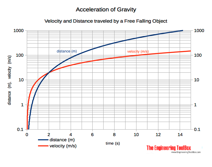
Acceleration of Gravity and Newton's Second Law
Transcribed Image Text. #1 #2 Variable input In this diagram, curves 1, 2, and 3 represent the: #3 O total, marginal, and average product curves, respectively total, average, and marginal product curves, respectively average, marginal, and total product curves, respectively marginal, average, and total product curves, respectivel) marginal ...
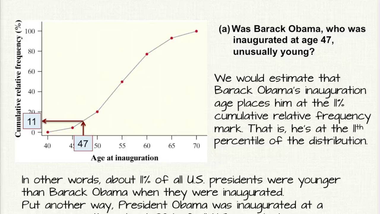
2.1 Cumulative Relative Frequency Graph Explanation - YouTube
Triple Point: The point O where all the three curves OC, OA and OB meet is known as triple At the triple point all the three phases of water system namely solid ice, liquid water and gas vapour are in equilibrium. The equilibrium in three phases is attained at 0.0076 0 C temperature and 4.58 mm Hg pressure. The degree of freedom will be : F = C - P + 2 = 1 - 3 + 2 = 0

Acid-Base Chemistry in the Presence of and Buffers—The ...
In the above figure, curves 1, 2, 3, and 4 represent the: A. ATC, MC, AFC, and AVC curves respectively. B. AFC, MC, AVC, and ATC curves respectively. ... The above diagram shows the short-run average total cost curves for five different plant sizes of a firm. In ...

Statistik: Kurtosis atau Keruncingan - Data Science
Utility Functions & Indiff CurvesUtility Functions & Indiff. Curves So the b ndles (4 1) and (2 2) are inSo the bundles (4,1) and (2,2) are in the indiff. curve with utility level U But the bundle (2,3) is in the indiff. curve with utility level Ucurve with utility level U 6. On an indifference curve diagram,
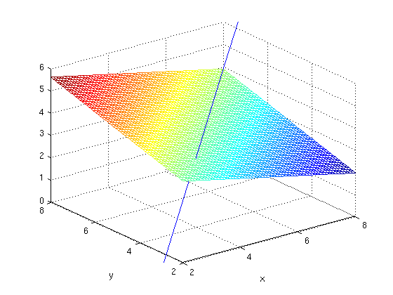
Lines, Planes and MATLAB
Thus, Fe – Fe 3 C diagram even though represents metastable conditions, can be assumed to represent equilibrium state relevant to the behaviour of most steels in practice. In cast irons, the high carbon content and the high silicon additions promote graphite formation and thus, in cast irons (except white cast iron) transformations are based much more on Fe-graphite diagram. …

Ch8, Lesson C, Page 10 - Adiabatic Compresion: TS and HS ...
3 2 x lny O 1.5,1.2 5.24,2.7 The variables xand ysatisfy the equation y2 = Aekx, where Aand kare constants.The graph of lnyagainst xis a straight line passing through the points 1.5, 1.2 and 5.24, 2.7 as shown in the diagram. Find the values of Aand kcorrect to 2 decimal places.[5]
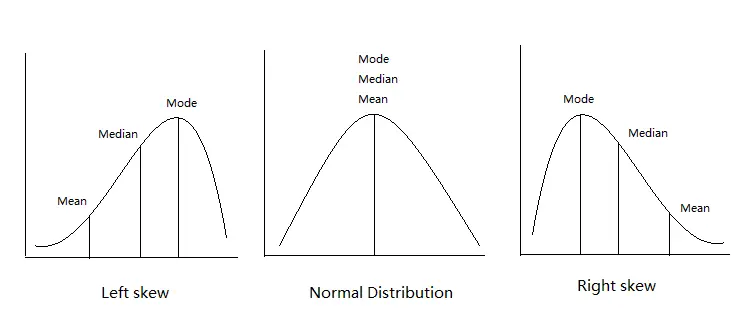
Excel central tendency (mean mode median)
possibilities curve. Part A Use Figures 1.1 and 1.2 to answer Questions 1 and 2. Fill in the answer blanks, or underline the correct answer in parentheses. 1. If the economy represented by Figure 1.1 is presently producing 12 units of Good B and zero units of Good A:

Rarefaction curves. Il.CON.1, 2, 3, 4, 5, and 6 mean ileal ...
Although the 3 curves are plotted for a wide range of volumetric flow rates, ... Different pump manufacturers have different formats for their pump curves diagram. Therefore, sometimes the pump curves can look a bit confusing at first. Sometimes there will be multiple lines on a single chart and you may not be sure about the meaning of each line. In such cases, always look for …
Gaussian Distribution
Download scientific diagram | A typical UCST-type phase diagram, curve 1, curve 2 and curve 3 represent crystallization temperature curve, spinodal curve and binodal curve, respectively from ...
3.0 Review of Lesson 2
4.1.1 Recognize a function of two variables and identify its domain and range. 4.1.2 Sketch a graph of a function of two variables. 4.1.3 Sketch several traces or level curves of a function of two variables. 4.1.4 Recognize a function of three or more variables and identify its level surfaces. Our first step is to explain what a function of ...

3D Arrows Step Diagram Template for PowerPoint - SlideModel
Why MR Curve of a price taking firm is perfectly elastic and equal to AR? (Use diagram) 41. ... Construct a pie diagram to represent the cost of construction of a house in Delhi Items Expenditure (in%) Labour 25 ... Capital goods 0.3 Others 2.0 100 32. Represent the following data with the help of suitable bar diagram : Year 2009 2010 2011 2012
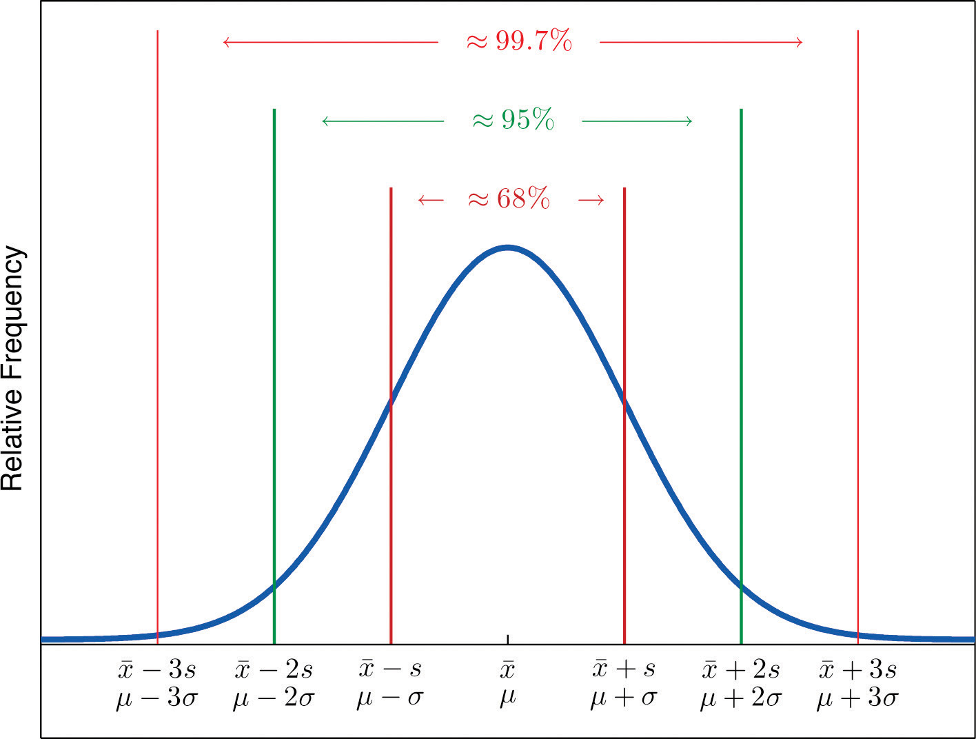
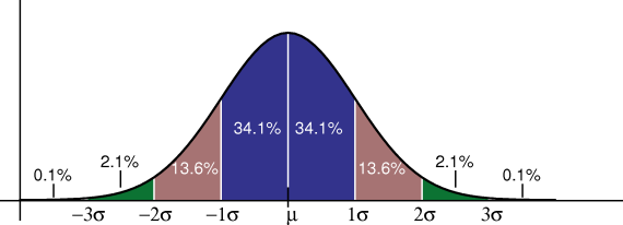
The Empirical Rule and Chebyshev's Theorem
C = 100 + .5 Y_D I = 100 + .1 Y - 500 i G = 100 T = .2 Y The public holds one-third of its money in currency (c = 1/3) and two-thirds of its money in checkable deposits. Banks hold one-quarter of ...

Position-Time Graph: Position-Time Graph
(b)€€€€ Draw, with labelled axes, a curve to represent the Maxwell-Boltzmann distribution of molecular energies in a gas. Label this curve T 1. On the same axes, draw a second curve to represent the same sample of gas at a lower temperature. Label this curve T 2. Use these curves to explain why a small decrease in temperature can lead ...

Indifference Curves: Meaning and Assumptions (With Diagram)
Unit 1, 2 &; 3 Exam Practice Unit 1-3 Exam Practice Page 6 Base your answers to questions 39 through 42 on the information below. Given the heating curve where substance X starts as a solid below its melting point and is

Behavioral Statistics in Action
Consider the following cost curves. (1) $ per unit of output (2) (3) Quantity In this diagram, curves 1, 2, and 3 represent the: 0 average variable cost, average cost, and marginal cost Total cost, total fixed cost and total marginal cost marginal cost, average cost, and average variable cost total marginal cost, total cost, and total variable cost

Isoquant and Isocost Lines (With Diagram) | Economics
(d) Constant temperature lines represent isothermal processes. Simple Vapour Compression Cycle on P-h Chart: A simple vapour compression cycle is shown by 1—2—3—4—1 on P-h chart of Fig. 36.24. 1- 2 Isentropic compression in compressor. 2- 3 Constant pressure cooling (Heat rejection). 3- 4 Isenthalpic expansion through expansion valve.

ins:billow926
1 The solid and liquid phases of water can exist in a state of equilibrium at 1 atmosphere of pressure and a temperature of (1) 0 o C (2) 100 o C (3) 273 o C (4) 373 o C ANSWER--->
:max_bytes(150000):strip_icc()/dotdash_Final_Production_Possibility_Frontier_PPF_Apr_2020-01-b1778ce20e204b20bf6b9cf2a437c42e.jpg)
Production Possibility Frontier (PPF) Definition
In the diagram, curves 1, 2, and 3 represent: a. average variable cost, marginal cost, and average fixed cost respectively. b. total variable cost, total fixed cost, and total cost respectively. c. total fixed cost, total variable cost, and total cost respectively. d. marginal product, average variable cost, and average total cost respectively.

PV Performance Modeling Collaborative | Spectral Content
These curves represent the relationships between phase-transition temperatures and pressures. The point of intersection of all three curves represents the substance's triple point—the temperature and pressure at which all three phases are in equilibrium.
What is the meaning of the B, C, and D curve in MCB? - Quora
A Venn diagram is a widely used diagram style that shows the logical relation between sets, popularized by John Venn in the 1880s. The diagrams are used to teach elementary set theory, and to illustrate simple set relationships in probability, logic, statistics, linguistics and computer science.A Venn diagram uses simple closed curves drawn on a plane to represent sets.
Does river stage tell you how much water is flowing? Water ...

Tesla Model 3 interior

An icon of business at Canary Wharf in London.

How do you graph a perfectly competitive resource market ...

Curves Γ (c, q 1 , q 2 ) given by Lemma 3, for fixed ...

BBC - GCSE Bitesize: Distance-time graphs

Preparation and Characterization of UiO-66 and Its ...

Two point charges, Q_1 and Q_2 are positioned at a certain ...

Fundamentals of laparoscopic surgery (FLS) task ...

Refer to the Figure below. The three average total cost ...
Exam 2 Study Guide - SCIENTIST CINDY

MEDIAN Don Steward mathematics teaching: cumulative ...
Left Tailed Test or Right Tailed Test ? How to Decide in ...
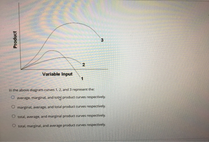
Solved: 0 2 Variable Input In The Above Diagram Curves 1 ...
0 Response to " in the diagram, curves 1, 2, and 3 represent"
Post a Comment