42 remote start wiring diagram
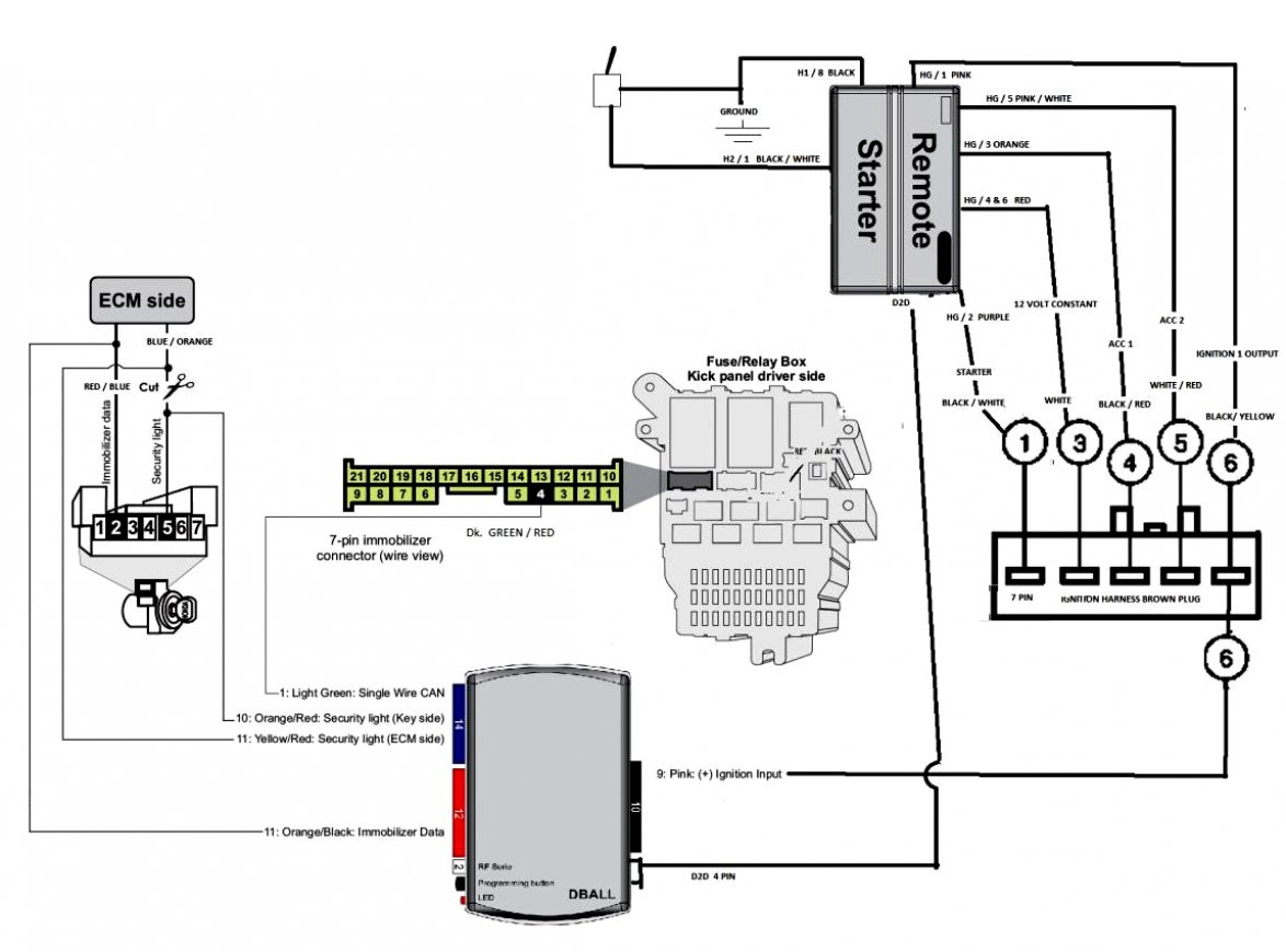
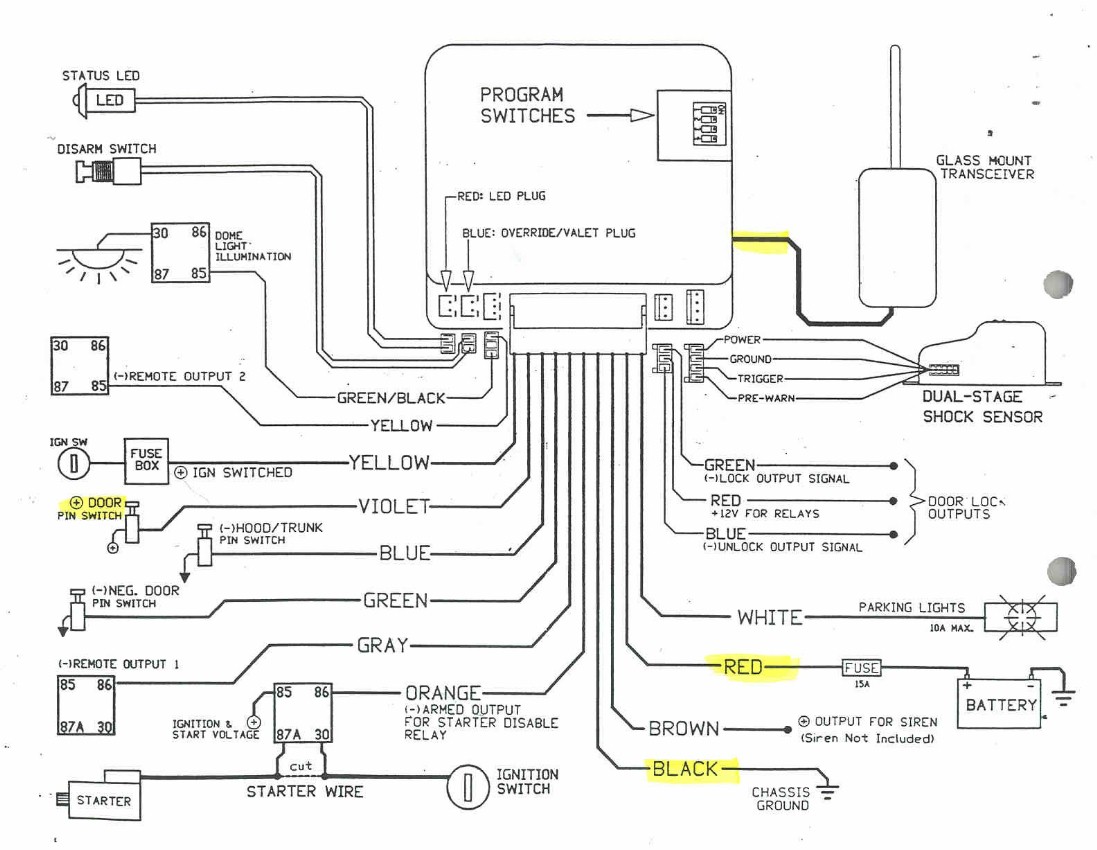
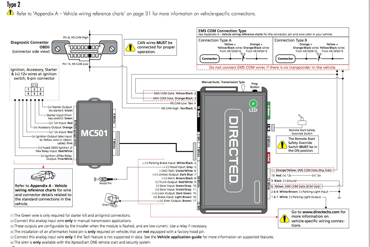
As stated earlier, the traces at a Viper Remote Start Wiring Diagram represents wires. Occasionally, the wires will cross. But, it does not mean connection between the cables. Injunction of two wires is usually indicated by black dot at the intersection of two lines. There will be main lines that are represented by L1, L2, L3, and so on. Uploaded by.Wiring Diagram D2D Port (for external Directed interface module) ON IMPORTANT! Remote Start Shutoff switch must be plugged in and in the ON position Thermistor/Temp Sensor Bitwriter/Directed SmartStart Port Door Lock 3-pin Harness Remote Start 8-pin Harness Main 6-pin Harness (+) or (-) LIGHT FLASH POLARITY (10A (MAXIMUM).
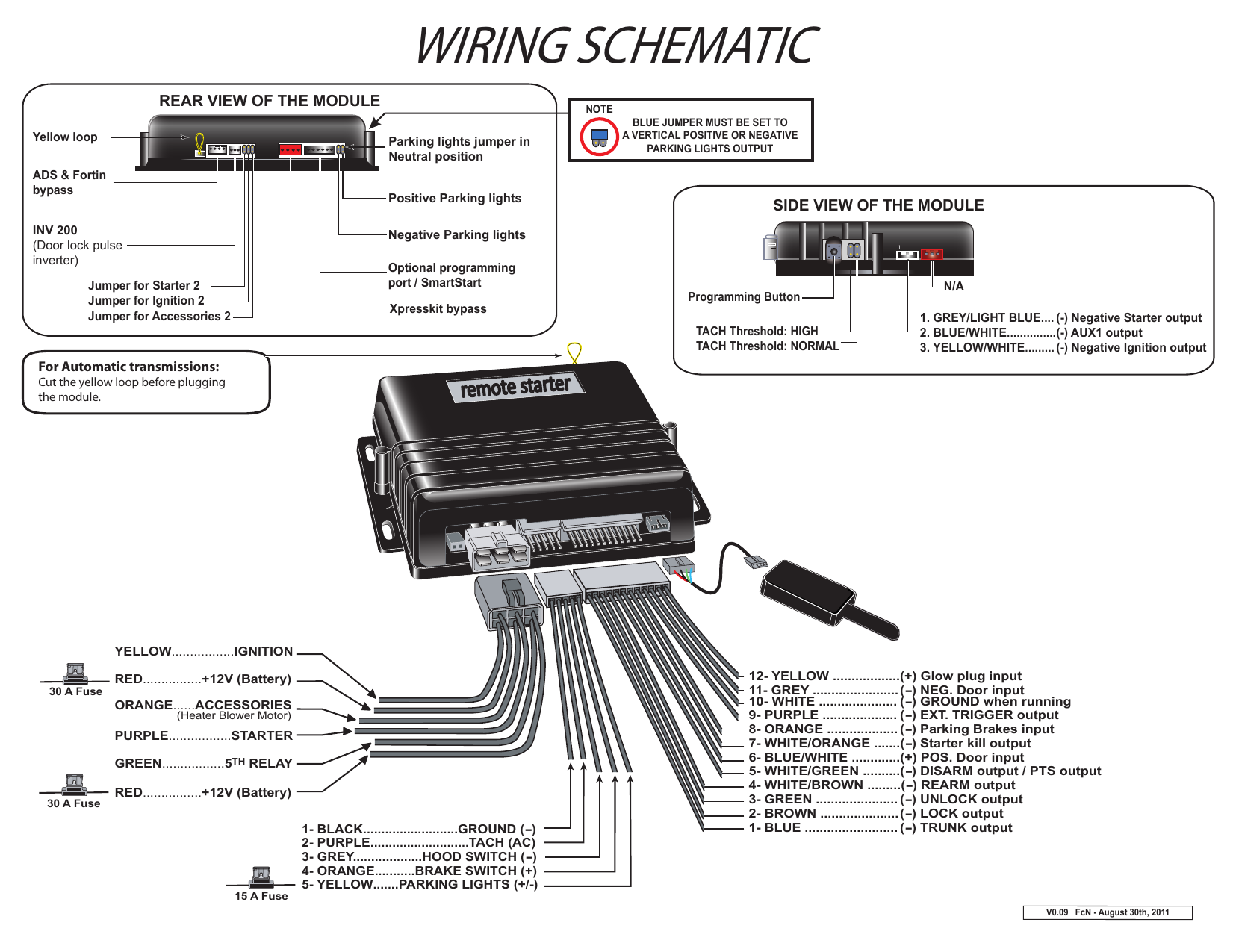
Tach learning procedure: When using tach mode this must be done before the first remote start attempt. Learn tach by: (1. ) S tarting the vehicle with the key, (2.) P ress and hold the foot brake, then (3. ) Activate the remote start sequence -one chirp and parking light flash indicates that the vehicle tach signal has been successfully learned.

Remote start wiring diagram
Jan 12, 2015 · I want to be helped with a wiring diagram of an ECU that incorporates an immobilizer, and the colour coding, then how I can isolate the immobilizer by removing the connections to immobilizer, so that I can start the vehicle, for Mazda 6, Atenza, 2008 model Start Remote 21 2/13 43 Local 1 3/14 Stop (OFF) Start (ON) ... Wiring Diagrams Reversing Starter Reversing Starter — Non-combination Reversing Starter — Combination F R F R F R A1 4 2 (If Used) A2 A1 5 7 3 6 A2 1 OL Remote Control Stations Starter Elementary Diagram L1 L2 L3 AC Suraielec Wireless Remote Light Switch, No Wiring, No WiFi, 100ft RF Range, Pre-Programmed, Expandable Wireless Wall Switch and Receiver Kit, Remote Control Light Fixture for Lamp, Ceiling Light, Fan 4.4 out of 5 stars 66
Remote start wiring diagram. Remote Start Relay Diagram - Basic Only 63 Starter Kill - Normally Closed 64 Starter Kill - Normally Open 65 Starter Kill - Passive with Horn Output and Horn Interrupt 66 Starter Kill - Passive with Remote Turn On Lead 67 Starter Kill - Passive with Switch 68 Stereo to Bridged Mono Switched Outputs 69 The avital green wire I tied to the GRAY wire running to the key switch. The avital purple ties to the other end of the GRAY wire running to the engine starter. This wire is at the top of the connector. The last pic shows a convenient wiring diagram I did to identify all the heavy gauge wires for the remote start module. Wiring diagrams for the various configurations are below. If you are unsure, please feel free to contact us. We are happy to explain further or talk about custom options if you don't see what you're looking for. Figure 1: Parts JCXX06P1X-XX - 3phase Starter with Start/Stop button, direct- online wiring diagram Collection of remote car starter wiring diagram it is possible to download at no cost. Please download these remote car starter wiring diagram by using the download button, or right click on selected image, then use Save Image menu. Wiring diagrams help technicians to view the way the controls are wired to the system.
Free Vehicle Wiring Search. Commando Car Alarms offers free wiring diagrams for installing your alarm, remote car starter, keyless entry or power door locks in your car or truck. View our complete listing of wiring diagrams by vehicle manufacture. Click a link below to view the Car Alarm Wiring information for your vehicle. (2-Wire Maintain) Evolution 2.0 Controller 12V Gen Battery Bottom of Evolution Controller Harness end Generac Remote Start Instructions of connector 1. Open the generator lid. Set the main switch on the generator to the OFF position. 2. Remove the 7.5-amp fuse from the top of the control panel. 3. Remove the front panel from the generator ... February 15, 2020 at 12:58 pm #194957. Here's the wiring diagram for earlier electric start 9.9/15 horse motors to help give you an idea what is what under the hood. It should apply to your '84 model to except for the ignition system. This reply was modified 1 year, 11 months ago by Mumbles . Wiring diagram to control LEDs with IR remote, receiver and Arduino. The LEDs are connected to pins 2 to 5 of the Arduino and the output of the IR receiver to pin 6. I used some 470 Ω resistors to limit the current going through the LEDs. The usual operating current of 3 and 5 mm LEDs is around 20 mA.
Yellow/Black Tach/Alternator sensing wire to remote start the vehicle. Tach learning procedure Page 6 To Learn Tach: STEP 1. Start the vehicle with the key and allow it to idle down STEP 2. Press and hold the foot brake STEP 3. While holding the foot brake, hold the remote start button on the remote for 3 seconds ... After the remote start module has been installed, test the remote start module in accordance with the Safety Check outlined in this installation guide. If the vehicle starts when performing the Neutral Safety Shutdown Circuit test, the remote start unit has not been properly installed. The remote start module must The Modified Life staff has taken every car remote start wiring diagram, car remote start wireing Avital L Avistart Remote Start with Two 4-Button Controls. Directed Remote Start systems are intended for fuel-injected, automatic transmission . Please refer to your vehicle wiring diagram for specific wire information. Directed Db3 Wiring Diagram Wiring diagram with T-Harness (THNISS3/THNISS3D) This testing should be performed by an authorized Directed dealer in accordance with. Directed Remote Start systems are intended for fuel-injected, automatic transmission . Please refer to your vehicle wiring diagram for specific wire information.
remote starter wiring diagram - You'll need an extensive, expert, and easy to know Wiring Diagram. With this sort of an illustrative guide, you'll be able to troubleshoot, stop, and total your tasks easily. Not merely will it help you attain your required final results more quickly, but also make the complete method less difficult for everybody.
Help and Additional Resources: • Alarm and Remote Start Manuals. • Alarm and Remote Start Pictorials. • Car Audio Forum. • Car Security & Convenience Forum. • Car Security & Convenience Hot Topics. • How to Determine Door Lock Types. • Relay Wiring Diagrams. • Vehicle Wiring Information & File Requests.
• The red plug on the end of the brown wire gets plugged in to the 'Sat Relay Port' of your remote start. This is how the remote start activates the bypass when it is needed. • The Red wire gets connected to a constant +12v power source. You can tap it directly on to the large red wire in the remote start's 6-pin harness.
Having a remote start wiring diagram makes installing a remote starter easy. Honda Eu7000is Remote Plug With Harness By Pinellas Power Products. Starter Wiring Help Electrical Circuit Diagram Wire Electricity Wiring diagrams sometimes called main or construc-tion diagrams show the actual connection points for the wires to the components and terminals of the controller. Remote […]
Remote Starter Wiring Colors and Notes. Function Vehicle Color Location. Start: YELLOW/DARK BLUE. Ignition #1: DARK BLUE/GRAY IGNITION SWITCH HARNESS. Ignition #2: ORANGE/BLACK IGNITION SWITCH HARNESS (HEAT-A/C) Ignition #3: N/A. Accessory: BLACK/WHITE IGNIITON SWITCH HARNESS (RADIO/WIPER) Brake Light: WHITE/TAN (+) SWITCH ON BRAKE PEDAL BRACKET.
In this Video I Go Over Car Alarm and Remote Start Wiring In Great Detail.Be sure to also watch my 5 part series / playlist on the installation job from star...
Logos. All information published in the vehicle diagram pages is gathered from sources which are thought to be reliable and accurate but we advise everyone check and verify our information by testing with a computer friendly test light to ensure proper connections are made. We at Access2Communications take pride in offering what we believe to ...
Feel free to use any Ford remote start wiring diagram that is listed on Modified Life but keep in mind that all the information here is provided “as is” without any warranty of any kind and most of the remote start wiring schematics listed on our enthusiast website are submitted by the Modified Life community. Use of the Ford wiring diagram is at your own risk. Always verify all wires ...
When the current is passed through the switch to the load, that is, bulbs, ceiling lights, etc. It makes the light turn ON. But when you push the button to OFF the light, it entirely breaks the circuit, and the passing of electricity is interrupted.
This wire turns on when the remote start button is pressed and stays on through the duration of the remote start. When using this wire for an Anti grind/Starter disable, an optional Relay is needed to interrupt the Starter circuit. The starter disable circuit prevents accidental grinding of the starter if key is turned too far after a remote start.
Refer to "Vehicle connections" following the wiring diagram. General notes: This section highlights important information for this specific firmware. [1] Tach wire is an optional connection required on some remote starters, which do not support a tach signal in D2D. [2] HS CAN 2 connections are required for heated seats.
Whether you're a novice GMC enthusiast, an expert GMC mobile electronics installer or a GMC fan, a remote start wiring diagram can save yourself a lot of time. The automotive wiring harness in a GMC is becoming increasing more complicated and more difficult to identify due to the installation of more advanced automotive electrical wiring. […]
Dec 22, 2021 · 2018 Honda CR-V, Remote Start Wiring - Good Evening, I have a 2018 Honda CR-V.. Normal key and I need the wiring diagram for it. Im doing a remote start/keyless..
Having a remote start wiring diagram makes installing a remote starter easy. Find the remote starter wiring diagram you need to install your car starter and save time. Scroll down and find the car start wire guide you need. It’s that easy! The best part? Every remote start wiring diagram contains information from other people who own the same car as you. If you want to install a new remote ...
Remote start wiring diagram. A wiring diagram is a simplified conventional pictorial depiction of an electrical circuit. Free vehicle wiring search. View our complete listing of wiring diagrams by vehicle manufacture. Find the remote starter wiring diagram you need to install your car starter and save time.
2006 TOYOTA Avalon Wiring Diagrams AVALON Push-Button Start, Engine Immobilizer & Steering Lock Electrical Wiring Diagram AVALON Ground Point Schematics
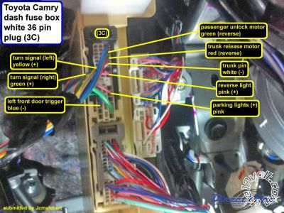
Listed below is the vehicle specific wiring diagram for your car alarm, remote starter or keyless entry installation into your 2004-2005 Dodge Ram . This information outlines the wires location, color and polarity to help you identify the proper connection spots in the vehicle. Please be sure to test all of your wires with a digital multimeter ...
quick installation diagrams t-harness to rs-700 and relay pack units: t-harness to deluxe 200, 500, and alert units with h1 plug: if 114 bypass passlock i diagram: if 114 bypass passlock ii diagram: if 114 bypass saturn bypass diagram: if 114 bypass transponder diagram: if 114 bypass vats diagram: ra-10 remote anything: rs-82: rs-82-85: rs-82i ...
Bulldog Security Remote Starter Wiring Diagram Diagram Remote Start Remote . Viper 791xv Wiring Diagram Trusted Wiring Diagrams In 2021 Diagram Wire Auto Start . Pin On Araba . 1969 Ford 3 Wire Alternator Diagram In 2021 Electrical Diagram Diagram Electrical Wiring Diagram . 2009 Toyota Corolla Alarm Wiring Data Wiring Diagrams Within 2009 Toyota Corolla Wiring Diagram Car Alarm Honda Civic ...
We will NOT respond to any requests by email. * Cruise control and navigation information such as Tach, Vehicle Speed Signal (VSS), and Brake wiring can often be found in the alarm/remote start information available. Please scroll down as some years are combined! (ex: 2010-17)
installation guide. If the vehicle starts in gear, cease remote start operation immediately and consult with the user to fix the problem immediately. After the remote start module has been installed, test the remote start module in accordance with the Safety Check outlined in this installation guide.
Suraielec Wireless Remote Light Switch, No Wiring, No WiFi, 100ft RF Range, Pre-Programmed, Expandable Wireless Wall Switch and Receiver Kit, Remote Control Light Fixture for Lamp, Ceiling Light, Fan 4.4 out of 5 stars 66
Start Remote 21 2/13 43 Local 1 3/14 Stop (OFF) Start (ON) ... Wiring Diagrams Reversing Starter Reversing Starter — Non-combination Reversing Starter — Combination F R F R F R A1 4 2 (If Used) A2 A1 5 7 3 6 A2 1 OL Remote Control Stations Starter Elementary Diagram L1 L2 L3 AC
Jan 12, 2015 · I want to be helped with a wiring diagram of an ECU that incorporates an immobilizer, and the colour coding, then how I can isolate the immobilizer by removing the connections to immobilizer, so that I can start the vehicle, for Mazda 6, Atenza, 2008 model















0 Response to "42 remote start wiring diagram"
Post a Comment