41 pump control panel wiring diagram schematic
Pump Control Panel Wiring Diagram Schematic - wiring diagram is a simplified conventional pictorial representation of an electrical circuit. It shows the components of the circuit as simplified shapes, and the capability and signal associates amid the devices. A wiring diagram usually gives guidance roughly the relative face and concord of ... B. Electrical schematic shall be plastic laminate affixed inside the control panel door. C. Electrical control panels shall be of sufficient size to house all control equipment. All panel penetrations for conduit shall be from the bottom. D. A double throw walking beam transfer switch shall be mounted inside the main control panel.
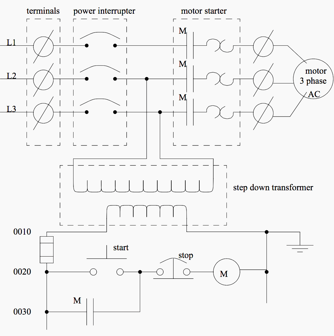
Electrical wiring diagrams of a PLC panel. ... it does tend to become more complex. Figure 5 below shows a schematic diagram for a PLC based motor control system, similar to the previous motor control example. ... are you able to make pump control repeater panels from the existing pumps to new repeater given a wiring diagram with specs.
Pump control panel wiring diagram schematic
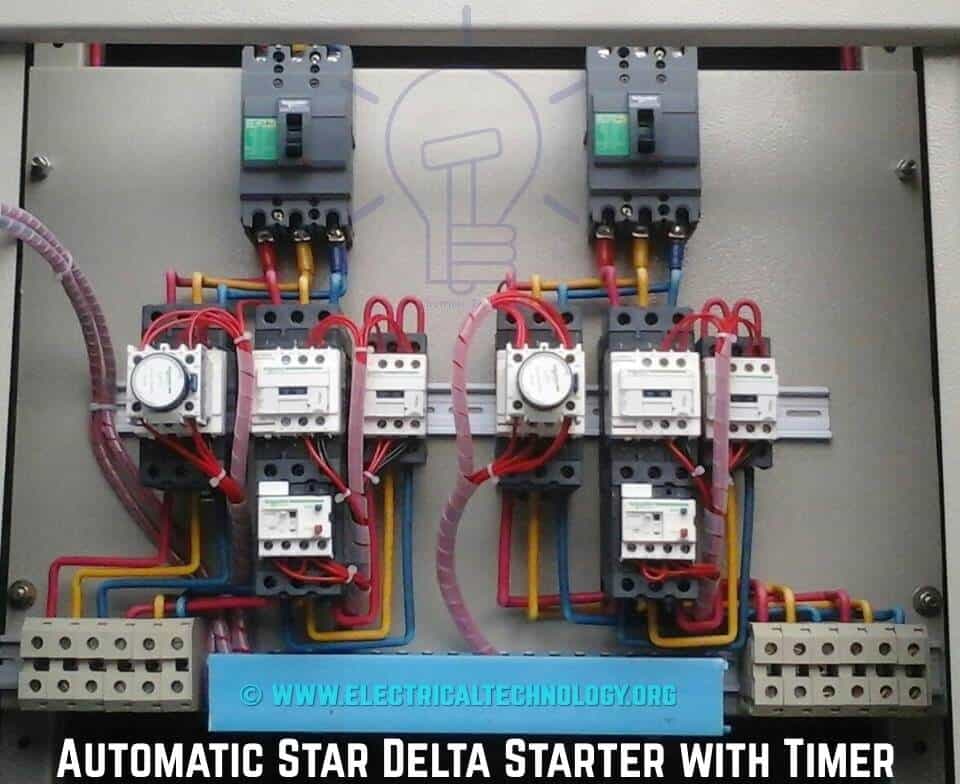
Components Disconnects (Fuse vs. Breakers) Generator Provisions Motor Protection (Fuses, Breakers, Thermal) Motor Controls (Starters, Soft Starters, Drives) Transformers Logic (Relay, Controllers, PLC) Alarm Dialers / Telemetry Pilot Devices Intrinsically Safe Pump Control Panel Wiring Diagram Schematic. Assortment of pump control panel wiring diagram schematic. A wiring diagram is a simplified traditional photographic depiction of an electric circuit. It shows the parts of the circuit as simplified shapes, as well as the power as well as signal links between the devices. A wiring diagram typically provides info… Control Box Wiring Diagrams AND OTHER CONTROL RELAY. 1. 2. 5. RED. YEL. START CAP. MFD. V. RUN. Technicians should test a well pump's control box before pulling a nonworking pump from the well. Well pumps with control boxes have start and run circuits. Visually inspect the control panel's wires, wire connections, relay and capacitor .
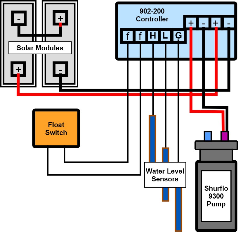
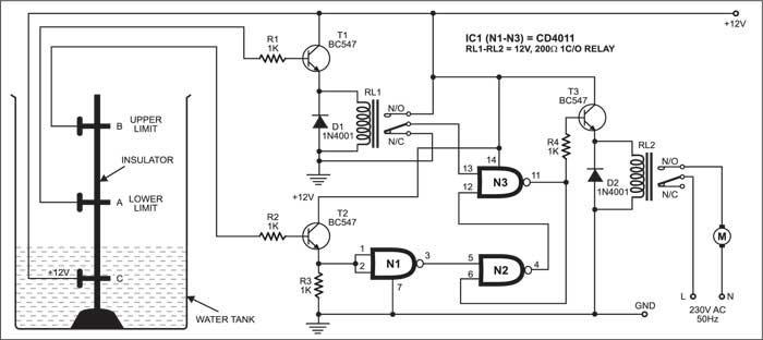
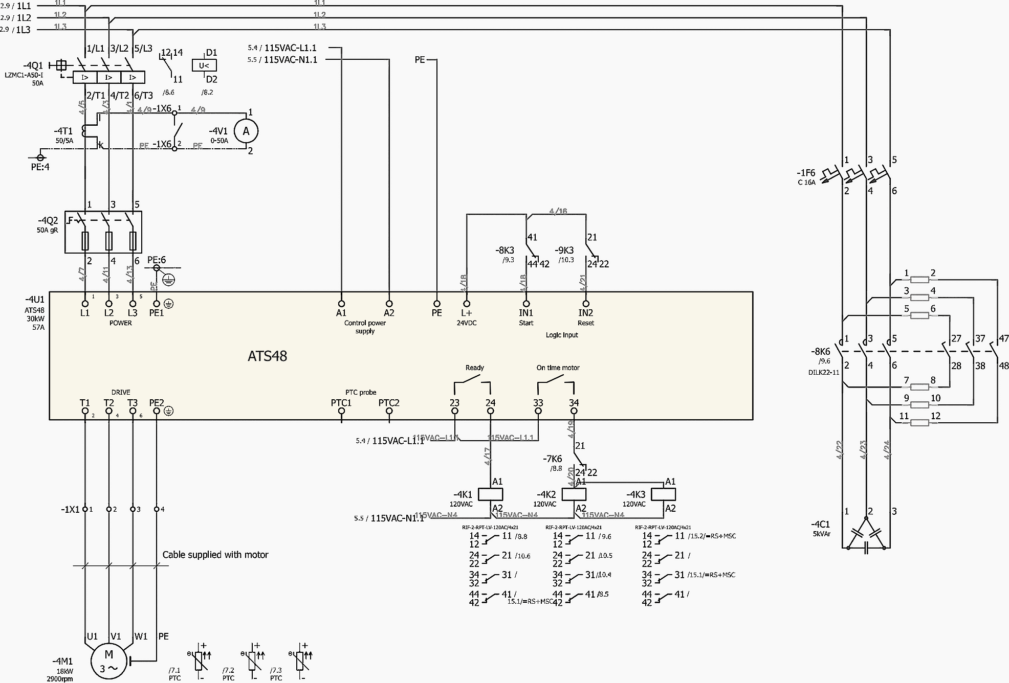
Pump control panel wiring diagram schematic. Septic Tank Float Switch Wiring Diagram Site Resource. 220 Wiring Float Switch Setup For Septic Effluent Pump Green Tractor Talk. Tran T2 Aerobic Septic Control Panel With Timer Pressure Sensor Tg Wastewater. 220 Wiring Float Switch Setup For Septic Effluent Pump Green Tractor Talk. Spi Bio Pump Control Panel With High Water Alarm Model 50b010 ... 3 phase submersible pump control panel circuit diagram. It has inbuilt single phase. A wiring diagram is a streamlined standard pictorial depiction of an electric circuit. 240 volt well pump wiring diagram wiring diagram is a simplified all right pictorial representation of an electrical circuit it shows the components of the circuit. PUMP STATION TO 22kW (SOFT STARTER) - COMMS - ELECTRICAL SCHEMATIC DIAGRAM. SASPI0014 ... AVOID SHORT CIRCUIT IF ... REMOTE CONTROL PANEL LCP 501. 175G0096.42 pages Dec 19, 2016 - A platform to learn electrical wiring, single phase, ... Types of Motor Control Schematics Info Mechanics PICS Electrical Panel Wiring, ...
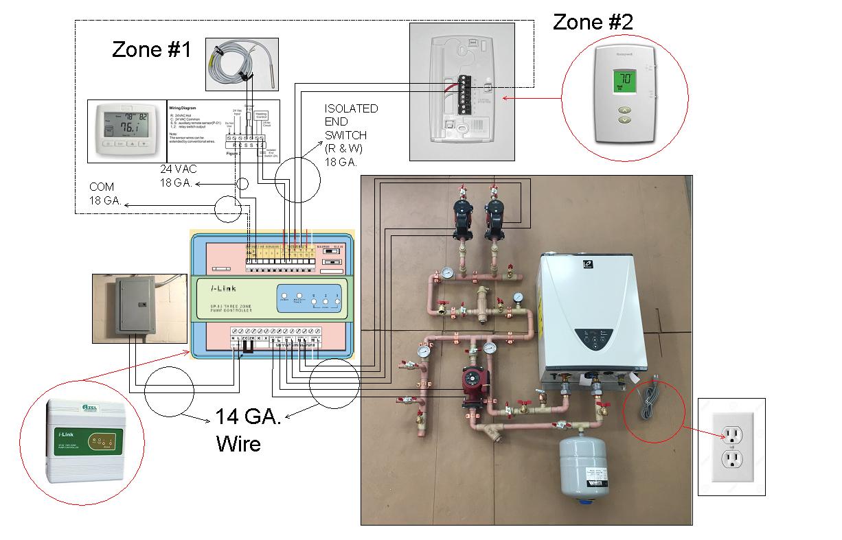
Wiring diagrams show the connections to the controller, while line diagrams show circuits of the operation of the controller. Standardized symbols. Booster Pump Control Panel Wiring Diagram from ars.els-cdn.com Effectively read a cabling diagram, one has to find out how the particular components within the program operate. For example , in case a module is powered up and it sends out a signal of fifty percent the voltage and the technician will not know this, he'd think he has a problem ... 3 Phase Water Pump Control Panel Wiring Diagram. angelo. June 19, 2021. 3 Phase Wiring Diagram For House Http Bookingritzcarlton Info 3 Phase Wiring Diagram Fo Electrical Circuit Diagram Electrical Wiring Basic Electrical Wiring. Submersible Pump Control Box Wiring Diagram For 3 Wire Single Phase Submersible Pump Submersible Well Pump Submersible. Connect the wires coming from the pumps to the pump terminals. Refer to the panel wiring diagram for the correct terminal connections for your system. 3. Connect the incoming power to the panel. Power to the panel must be appropriate to the control panel and pump motor (120 VAC, single-phase for a 120 VAC motor, 240 VAC single-phase for a 240
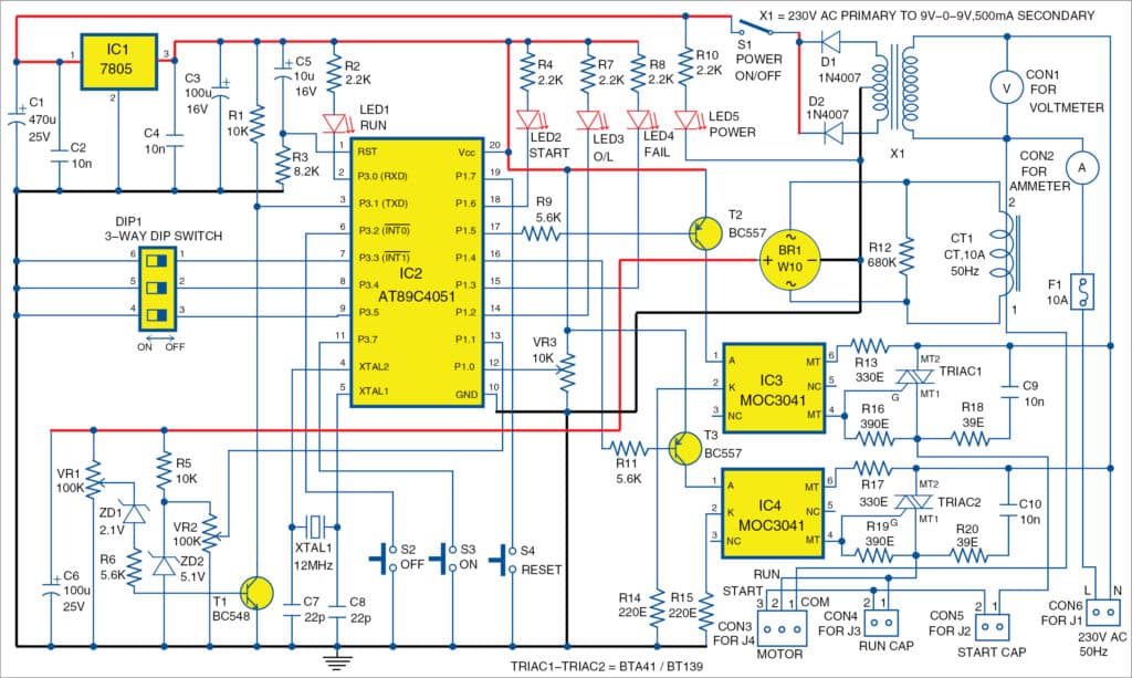
4. Locate the booster pump control on a wall as close to the booster pump system as possible. 5. Follow all local plumbing and electrical codes. After guidelines have been met, connect the booster pump wiring to the motor contractor located in the control panel (ref control wiring diagram in the control panel). NEMA and IEC Markings and Schematic Diagrams...... 4. Control and ... Overcurrent Protection for 3-Wire Control Circuits ... Lettered Terminals in Panel.109 pages Single-phase submersible pump control box wiring diagram - 3 wire submersible pump wiring diagram. In the submersible pump control box, we use a capacitor, a resit-able thermal overload, and a DPST switch (double pole single throw). The wiring connection of the submersible pump control box is very simple. Here is the complete guide step by step. Note: In this publication the line diagrams show the control circuits only - power circuits are omitted for clarity, since they can be traced readily on the wiring diagrams (heavy lines). A wiring diagram gives the necessary information for actually wiring-up a group of control devices or for
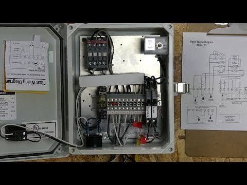
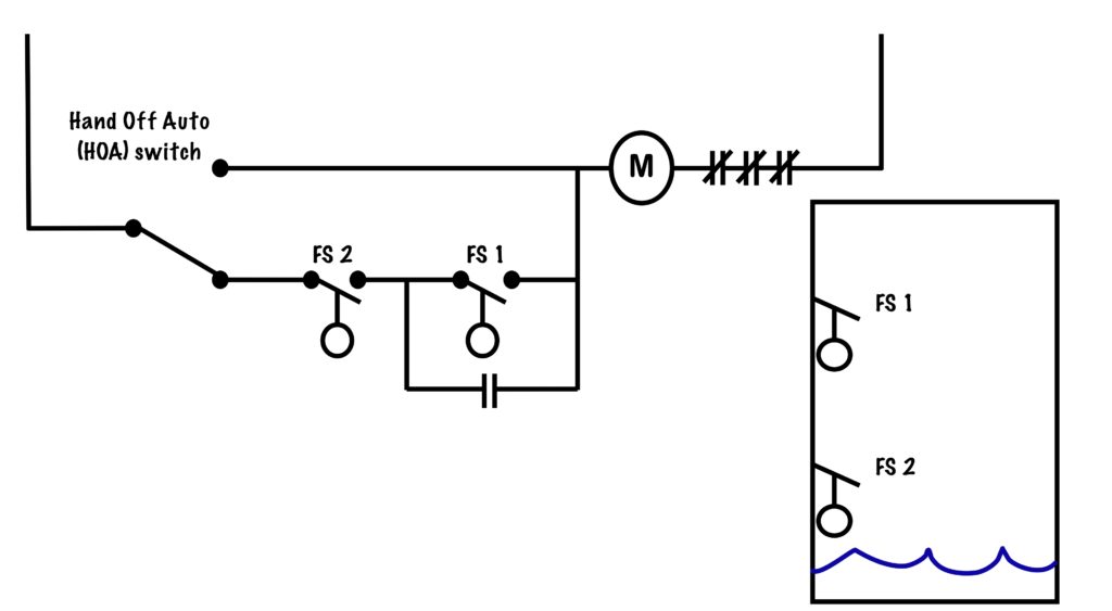
The control switch and the HOA switches may be turned off to provide an additional safety feature when servicing. These switches are located inside the panel to protect against activation by unauthorized personnel. Green pump run indicator lights located on control circuit board. Easy-to-follow wiring diagram and terminal strip provide for ...
Wiring diagrams for all control and electrical panels. Diagrams shall (e) Electrical schematic diagram of the pump station as supplied, prepared in. Economy Duplex Sump Pump Control The duplex control provides alternating operation of two volt pumps. Plug-in ready wiring makes installation easy! Simply plug the pumps into the provided receptacles.

Assortment of duplex pump control panel wiring diagram. A wiring diagram is a simplified traditional pictorial representation of an electric circuit. It reveals the components of the circuit as streamlined shapes, and also the power as well as signal links in between the gadgets.

Volume 10—Enclosed Control CA08100012E—November 2012 www.eaton.com ... Type 3R Industrial Pump Panel— ... Freedom—Fusible Disconnect and Circuit Breaker.29 pages
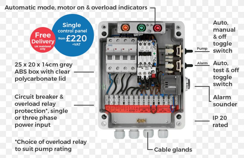
Control voltage is 120 VAC · Use IEC devices · 22mm pilot devices · Wallmount enclosure – outdoor rated · Main circuit breaker with door mounted operating handle ...
Float Switch Installation Wiring Control Diagrams Apg. Spi Duplex Time Dosing Control Panel 120 230v 50a810. Submersible Pump Wiring Diagram Control Panel Pumping Station Png. Sim A Single Phase Simplex Sump Pump Control Panel See Water Inc. Figure 4 42 Control Panel Wiring Diagram All Except Model 350 Pafn.

Duplex Pump Control Panel Wiring Diagram Sample. Variety of duplex pump control panel wiring diagram. A wiring diagram is a streamlined traditional pictorial depiction of an electric circuit. It shows the parts of the circuit as simplified forms, and the power as well as signal connections between the gadgets. A wiring diagram normally provides info about the…

Wiring Diagram Electrical Wires Cable Schematic Sump Pump Png 1080x897px Area Harness. Sump pump control panel wiring diagram how to create a circuit fill controller float switch installation switches pilot devices solid state submersible single phase simplex automatic water full 3 bat waterproofing ups for back up electrical wires cable tank ...

Duplex Pump Control Panel Wiring Diagram Schematic. Duplex 115 208 230v 1 phase control panel three alternating pump m sprecher schuh custom lift station demand wd3p 4 booster controllers overview eaton sewage model 322 sje rhombus. Duplex Demand Control Panel 115 230v Single Phase Individual Pump Circuit Breakers Definite Purpose Contactor.

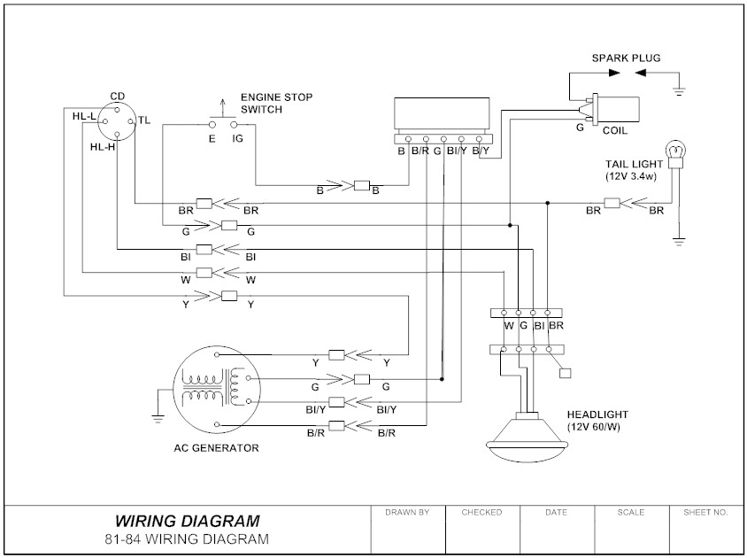
page 26 — st4/st6 series submersible pumps • operation anD parts manual — rev. #1 (11/12/13). CONTROL BOX WIRING DIAGRAM (CB1269/CB1274).2 pages
pump control panel wiring diagram schematic - What's Wiring Diagram? A wiring diagram is a schematic which uses abstract pictorial symbols showing each of the interconnections of components inside a system.

Pump Control Panel Wiring Diagram Schematic Sample. pump control panel wiring diagram schematic - Just What's Wiring Diagram? A wiring diagram is a kind of schematic which makes use of abstract photographic signs to show all the interconnections of components in a system. Electrical wiring diagrams are comprised of 2 things: signs that stand for the parts…

Figure 2 1 Control Panel Wiring Diagram Sheet Of 4. Submersible Pump Microcontroller Wiring Diagram Three Phase Electric Power Png 1000x648px Circuit Breaker. Control Panel For Submersible Molock Pumpset Pump Starter Circuit. Aim Manual Page 54 Single Phase Motors And Controls Motor Maintenance North America Water Franklin Electric.

Franklin Electric Well Pump Control Box Wiring Diagram - wiring diagram is a simplified standard pictorial representation of an electrical circuit. It shows the components of the circuit as simplified shapes, and the capability and signal connections with the devices. A wiring diagram usually gives counsel about the relative position and ...

Basics 7 4.16 kV 3-Line Diagram : Basics 8 AOV Elementary & Block Diagram : Basics 9 4.16 kV Pump Schematic : Basics 10 480 V Pump Schematic : Basics 11 MOV Schematic (with Block included) Basics 12 12-/208 VAC Panel Diagram : Basics 13 Valve Limit Switch Legend : Basics 14 AOV Schematic (with Block included) Basics 15 Wiring (or Connection ...

IDENTIFICATION OF BARNES STEALTH SERIES DUPLEX CONTROL PANEL FOR ESPS-200 LEVEL CONTROL WIRING To determine the proper wiring schematic you will need to fi rst determine the panel type you have using the information listed below. The information can be located inside the control panel door on the panel schematic.

for 20mA. See the wiring diagrams (Figures 7 & 8) at the end of this manual for the proper wiring of the current transmitter. 2.0 APPLICABLE DOCUMENTS none 3.0 REQUIREMENTS 3.1 GENERAL DESCRIPTION The Duplex Pump Control System (CPC-2) is a system that automatically controls one or two pumps in pump down type applications.
Panel must be ordered with the proper amp rating matching that of the pump. • Field wiring diagram, panel schematic and installa-tion instructions included. • Panel can be wired for a single power feed for pump and control circuit or the control circuit can be wired Z = Simplex dry contact for pump running interface to building management ...
Control Box Wiring Diagrams AND OTHER CONTROL RELAY. 1. 2. 5. RED. YEL. START CAP. MFD. V. RUN. Technicians should test a well pump's control box before pulling a nonworking pump from the well. Well pumps with control boxes have start and run circuits. Visually inspect the control panel's wires, wire connections, relay and capacitor .
Pump Control Panel Wiring Diagram Schematic. Assortment of pump control panel wiring diagram schematic. A wiring diagram is a simplified traditional photographic depiction of an electric circuit. It shows the parts of the circuit as simplified shapes, as well as the power as well as signal links between the devices. A wiring diagram typically provides info…

Components Disconnects (Fuse vs. Breakers) Generator Provisions Motor Protection (Fuses, Breakers, Thermal) Motor Controls (Starters, Soft Starters, Drives) Transformers Logic (Relay, Controllers, PLC) Alarm Dialers / Telemetry Pilot Devices Intrinsically Safe


0 Response to "41 pump control panel wiring diagram schematic"
Post a Comment