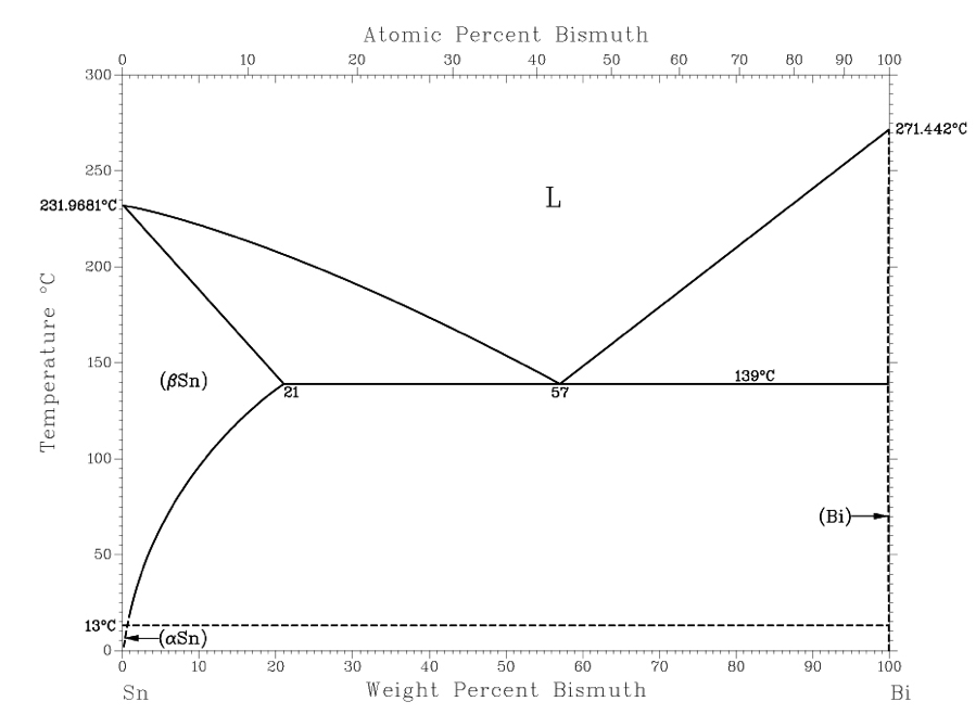
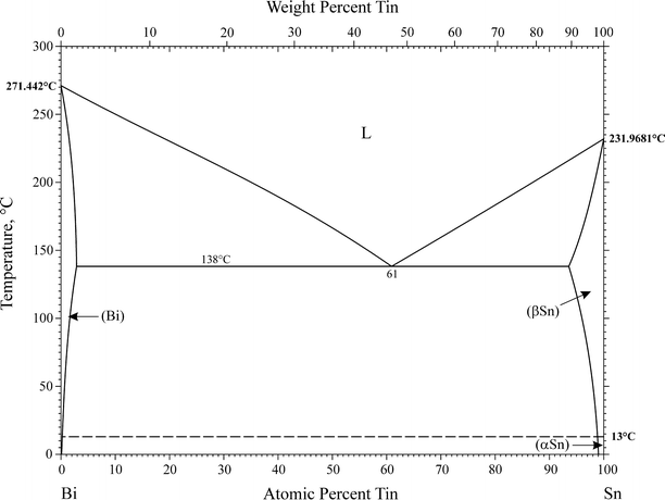
38 bismuth tin phase diagram
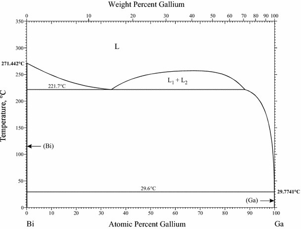
tin, which melts at 232oC. In low temperature soldering a number of alloying elements can be used to reduce tin's melting temperature. Ga, In, Bi, and Cd are effective in reducing the melting temperature of solder alloys, although Cd is not often considered due to its toxicity. Gallium-containing
Bismuth Tin Phase Diagram of eutectic tin-bismuth (Sn-Bi) solder were investigated. The investigation showed that, . addition equilibrium diagrams for each solder were deter- mined using. Cooling curves for bismuth-cadmium system. Equilibrium diagram of bismuth and cadmium. . eutectiferous series-tin--Mg Sn and Mg2Sn- magnesium.
Tin Bismuth Phase Diagram - Crystals Free Full the thermodynamic modeling of multi ponent phase equilibria the first term g 0 corresponds to the gibbs energy of a mechanical mixture of the constituents of the phase the second term g ideal corresponds to the Tin Bismuth Phase Diagram - Crystals Free Full

Bismuth tin phase diagram
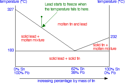
Important: This is a simplified version of the real tin-lead phase diagram.In particular, it ignores the formation of solid solutions of tin and lead. You will find the correct diagram on this NIST web page.Beware that on that page, the tin-lead axis is reversed from the one I have drawn above - in other words 100% lead is on the right rather than the left.
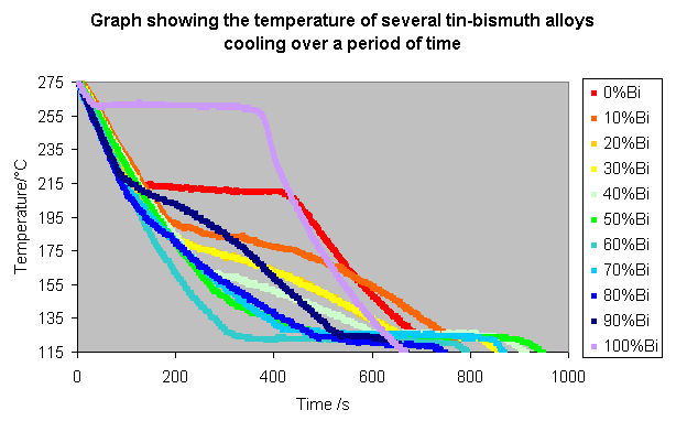
An experiment can be performed to get a rough idea of a phase diagram by recording cooling curves for alloys of two metals, in various compositions. The alloy chosen for this example is bismuth-tin, both of which metals have low melting points, and so can be heated and cooled more quickly and easily in the lab.
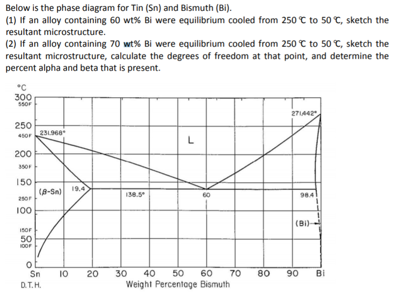
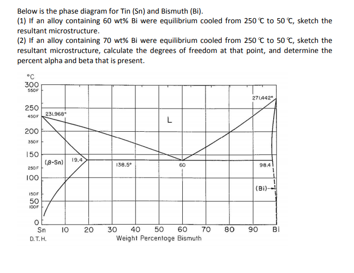
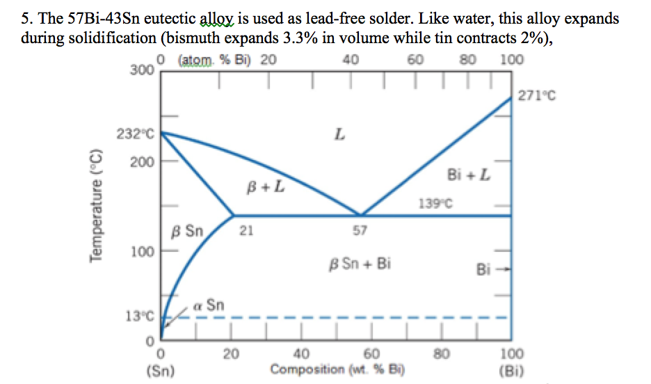
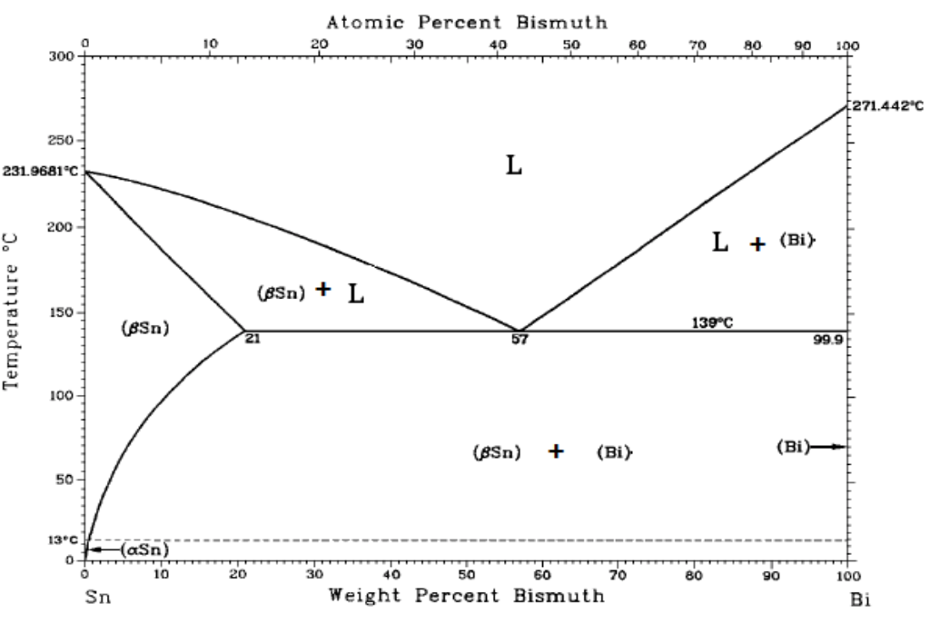
Over here, single phase solid solution. Bismuth with a small amount of tin in it. And in these various two phase regions up above, this horizontal temperature range, we find that this part of the map, this region is liquid plus beta, liquid and beta being the adjacent basis.
Bismuth tin phase diagram.
THE BI-SN EQUILIBRIUM PHASE DIAGRAM Mike Meier Department of Chemical Engineering and Materials Science University of California, Davis Davis, CA 95616 USA Key Words: equilibrium phase diagram, eutectic, thermocouple Prerequisite Knowledge: basic understanding of equilibrium phase diagrams, eutectic reactions, and temperature measurement using thermocouples.
low enough temp. that the phase diagram shows nothing more is going on. - read the graph accordingly to determine the temperatures used for the phase diagram. - repeat with each alloy sample. ... Sample # Bismuth Tin Sample # Bismuth Tin 1 100 0 1 10 0 2 97.5 2.5 2 9.74 0.25093 3 95 5 3 9.5153 0.4999 4 90 10 4 9.039 1.0065 5 70 30 5 7.0023 2.9719
The eutectic temperature and composition determine a point on the phase diagram known as 'eutectic point'. ... Tin-zinc or Cadmium-bismuth. Fig. 2.10 illustrates the equilibrium diagram of Cadmium-bismuth system. If a small amount of cadmium is added to molten bismuth, the freezing point of the resulting alloy is lowered, as indicated by ...
Reaction of substrate material that has been pre-tinned with a tin-lead or tin-bismuth alloy with a solder of a different composition may result in the formation of a low-melting higher-component eutectic. In this case, the multi-component phase diagram can be used to evaluate the possible effects resulting from such a contamination.
phase diagram 1 Articles . ... The braid wicks the bismuth-tin mix away from the leads along one side of the chip, while gravity pulls it down the braid to pool safely on the bench. Pretty slick.
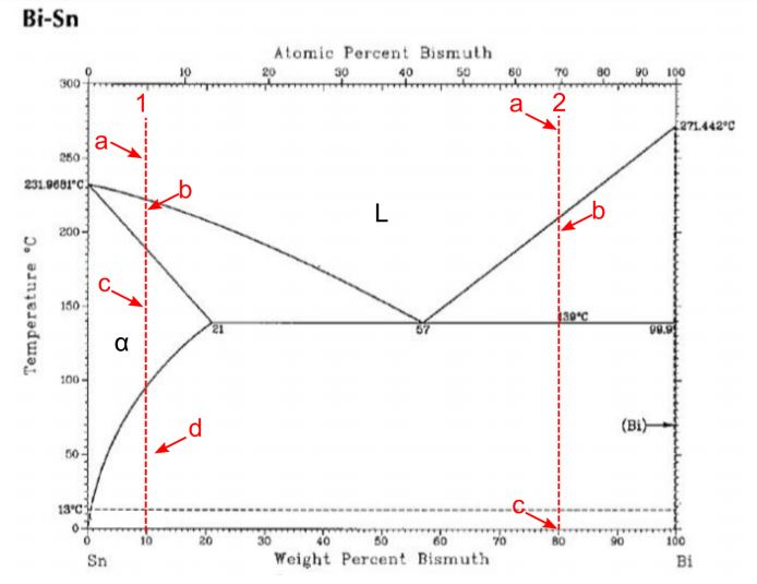
Fig. 7 THE BISMUTH-TIN PHASE DIAGRAM The diagram is based on published data (e.g. M.Hansen & K. Anderko, 'constitution of inary Alloys;' .J. Smithells, "Metals Reference Book"). There is a slight uncertainty in the eutectic composition, with most reports in the range of 42-43% Tin. The Alloy MCP 137 contains 42% Tin.
Bismuth Tin Phase Diagram bismuth chemical element bismuth bismuth bi the most metallic and the least abundant of the elements in the nitrogen group group 15 [va] of the periodic table bismuth is titanium aluminum ti al phase diagram the titanium aluminum ti al phase diagram calc... Continue Reading White Rogers Thermostat Wiring Diagram
84Sak: T. Sakurai, "Construction of the Bi−Pb−Sn Ternary Phase Diagram by Means of Thermal Analysis," dissertation (GIF049), School of Science and Engineering, Waseda University, Japan (1984) in Japanese. (Ternary System; Experimental; Indicates presence of a phase diagram)
prism is a two-component temperature-composition phase diagram with Pb Triple Eutectic 3-Dimensional Depiction of Temperature-Composition Phase Diagram of Bismuth, Tin, and Lead at 1atm. The diagram has been simplified by omission of the regions of solid solubility. Each face of the triangular a eutectic.
Status of the thermodynamic description: B.-J. Lee, C.-S. Oh and J.-H. Shim, J. Electron. Mater. 25 (1996) 983-991: Full thermodynamic assessment.
The phase diagram of PbBi alloys (Fig. 2) shows a large solid solubility of about - 17.5 wt.% Bi in Pb at room temperature. The solubility at a temperature of 184°C is 23.5 wt. %. An eutectic reaction involving the intermediate β phase and the Bi terminal phase
Tin-bismuth alloy nanoparticles were chosen for our first investigation of temperature-sensitive nanoparticles. This alloy has a melting temperature that is tunable between 139 ° C and 271 ° C by...
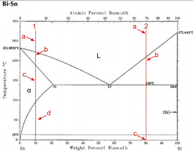
Civil Engineering questions and answers. QUESTION 30 Figure 3 shows the equilibrium phase diagram for the tin-bismuth binary alloy system What phases would be expected to be present in an alloy of composition 90 wt% Sn. 10 wt% BI held at 150°C? Assume equilibrium conditions apply. (1 mark) a) (B-Sn) b) (B-Sn) + L C) (B-Sn) + (BI) d) (BI) + L ...
Abstract. This article is a compilation of binary alloy phase diagrams for which bismuth (Bi) is the first named element in the binary pair. The diagrams are presented with element compositions in weight percent. The atomic percent compositions are given in a secondary scale. For each binary system, a table of crystallographic data is provided ...
on Bismuth Tin Phase Diagram. Diagram Type: binary phase diagram. Concentration range: full composition; 0- at.%. Sn. Temperature: - °C. Nature of investigation. Bio Hi everyone, my name is Josh and this is my first post, it is quite long but I hope you find it informative. by engenuity. 3 Metals Bi - Sn - Zi.
Bi-Sn (Bismuth-Tin) The Bi-Sn phase diagram in [Massalski2] was adopted from [Hansen], who assessed the Bi-Sn phase diagram data published before 1958. Since then, more experimental data on this system were reported by [ 1958Oel ], [ 1969Del ], [ 1987Gla ], and [ 2007Bra ].
From Wikipedia, the free encyclopedia Bi-In phase diagram. L stands for liquid. The elements bismuth and indium have relatively low melting points when compared to other metals, and their alloy bismuth-indium (Bi-In) is classified as a fusible alloy. It has a melting point lower than the eutectic point of the tin-lead alloy.
Bismuth -cadmium system. KCl -CaCl 2 system. Benzene - methyl chloride system. KI -H2O system. Lead -silver system. Lead -silver system. o It is an example for two components system. o Its phase diagram forms a simple eutectic point. o The eutectic point can be represented by point C in the above figure.
phase changes and to create an experimental phase diagram and 57wt% Bi would be the best fit for soldering as an replacement for traditional lead-tin solder. Key words primary soldering material, Sn-Bi alloys, Bismuth and Tin mixtures DSC, powder XRD, replacement for lead 1. Introduction
If you look closely at the Tin-Bismuth phase diagram or the lead bismuth phase diagram small amounts of bismuth will just go into a solid solution in the tin phase or the lead phase. For example ...
For a phase diagram to depict a binary system, it must contain at least two components in different phases such as nickel and copper or tin and bismuth. For all binary phase diagrams, a solid solution, liquid and a solid Chand 3 phases (or any combination of two) are depicted.
Allen and Jesser [49] evaporated 99.99% Bi and Sn on amorphous C films to make alloys with 40 nm grains, and observed them via using in situ TEM. Fig. 7.7 shows one of their phase diagrams. The solid and dashed lines show the phase diagrams of conventional and nanoalloys, respectively. In each of the nanoalloy phase diagrams the solidus and liquidus fully move down; therefore the melting point ...
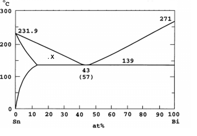
According to phase diagram of tin-bismuth binary system [75] the eutectic alloy contains 39.0 at.% of tin included into two crystalline phases of bismuth and -tin ( Figure 18). The latter...





![The Sn–Bi bulk phase diagram [20]. Points show the ...](https://www.researchgate.net/profile/Boris-Straumal/publication/253084994/figure/fig1/AS:393259974184969@1470771892125/The-Sn-Bi-bulk-phase-diagram-20-Points-show-the-compositions-of-the-studied-alloys-and.png)



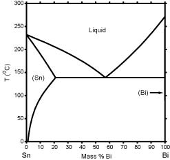


![The Sn–Bi bulk phase diagram [20]. Points show the ...](https://www.researchgate.net/profile/Boris-Straumal/publication/253084994/figure/fig1/AS:393259974184969@1470771892125/The-Sn-Bi-bulk-phase-diagram-20-Points-show-the-compositions-of-the-studied-alloys-and_Q320.jpg)


0 Response to "38 bismuth tin phase diagram"
Post a Comment