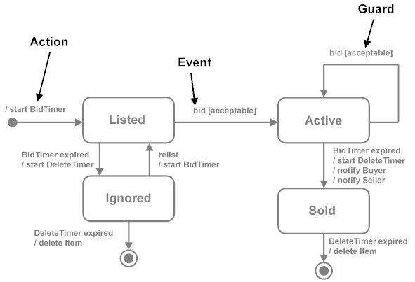
42 in a state transition diagram, the circle to the left is the final state.
In a state transition diagram, the circle at the right with a hollow border is the initial state. False. In a state transition diagram, the circle to the left is the final state. F 23. A class diagram resembles a horizontal flowchart that shows the actions and ...
A statechart diagram shows a state ... A final state is represented as a filled black circle surrounded by an unfilled circle. Initial and final states are really pseudostates. Neither may have the usual parts of a normal state, except for a name. A transition from an initial state to a final state may have the full complement of features ...

In a state transition diagram, the circle to the left is the final state.
Tutorial - 5 Steps to Draw a State Machine Diagram Page 5 of 11 7. Release the mouse button. In the popup pane, select Transit -> Final State. This creates a final state. 8. Click a self-transition on the state account with funds. Move your mouse pointer over the state account with funds and click on the Resource Catalog button. 9. State Machine Diagrams. State machine diagram is a behavior diagram which shows discrete behavior of a part of designed system through finite state transitions. State machine diagrams can also be used to express the usage protocol of part of a system. Two kinds of state machines defined in UML 2.4 are . behavioral state machine, and; protocol state machine A state diagram is used to represent the condition of the system or part of the system at finite instances of time. It's a behavioral diagram and it represents the behavior using finite state transitions. State diagrams are also referred to as State machines and State-chart Diagrams.These terms are often used interchangeably. So simply, a state diagram is used to model the dynamic behavior ...
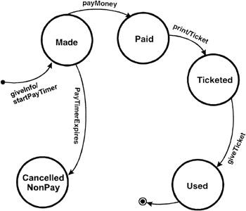
In a state transition diagram, the circle to the left is the final state.. In a state transition diagram, the circle at the right with a hollow border is the initial state. True/False. Answer: False. In a state transition diagram, the circle to the left is the final state. True/False. Answer: False. Topic Covered. State Transition Diagram with example in software engineering. Label the transition with the event that triggered it and the action that results from it. A state can have a transition that points back to itself. Initial State A filled circle followed by an arrow represents the object's initial state. Final State An arrow pointing to a filled circle nested inside another circle represents the object's final ... In the normal transition diagram, the initial state is represented by a circle with an arrow pointing towards it, the final state by two concentric circles and the other states are represented by just a circle. ADVERTISEMENT. Types of finite Automata. Click on "Shapes" in the upper-left corner of your window and check "UML.". The UML shape libraries will then appear on the left side of your window. Scroll down for the state diagram library and drag out a black circle to start the diagram. This circle indicates the initial state. Diagramming is quick and easy with Lucidchart.
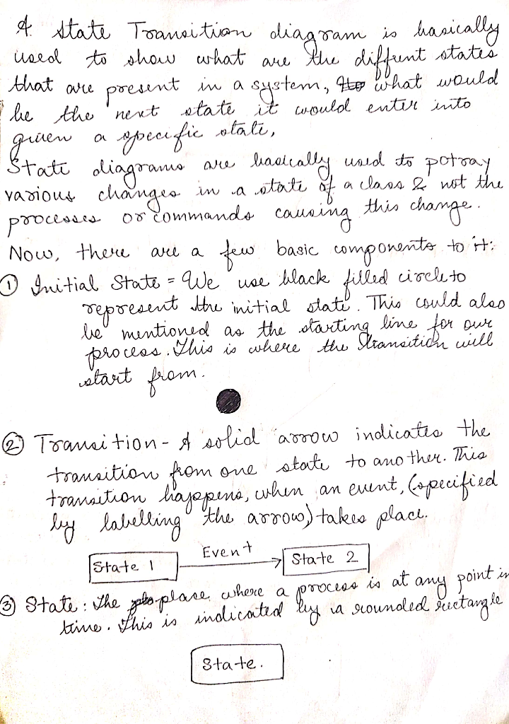
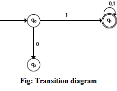
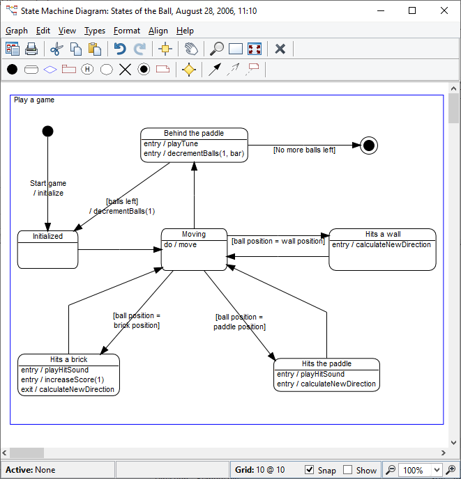
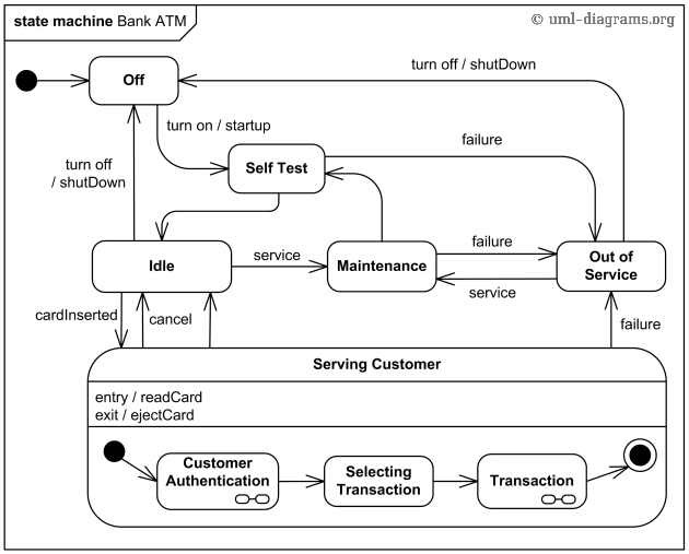
The transition diagram is also called a transition graph; it is represented by a diagraph. A transition graph consists of three things: Arrow (->): The initial state in the transition diagram is marked with an arrow. Circle : Each circle represents the state. Double circle : Double circle indicates the final state or accepting state. Transition ... An initial state, also called a creation state, is the one that an object is in when it is first created, whereas a final state is one in which no transitions ... A state is denoted by a round-cornered rectangle with the name of the state written inside it. Initial and Final States. The initial state is denoted by a filled black circle and may be labeled with a name. The final state is denoted by a circle with a dot inside and may also be labeled with a name. Transitions How to draw a state diagram. Each diagram usually begins with a dark circle that represents the initial state and ends with a bordered circle that represents the final state. States are denoted with rectangles with rounded corners. Each rectangle is labeled with the name of the state. And transitions are marked with arrows that link one state ...
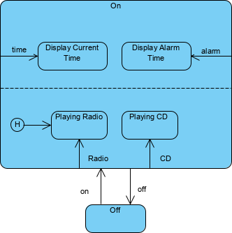
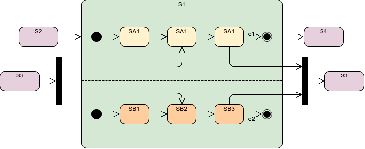
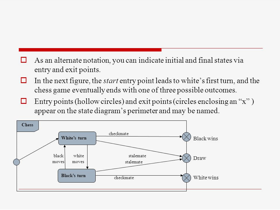
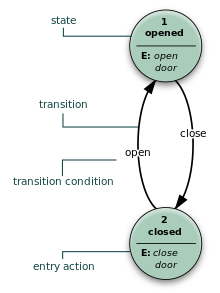
The bar may have one or more arrows from source states to the bar. A transition string may be shown near the bar. Final State: Transition to final state. Final state is a special kind of state signifying that the enclosing region is completed. Final state is shown as a circle surrounding a small solid filled circle. Protocol State Machine State Transition Diagram for an ATM System. uccState Transition Diagram are also known as Dynamic models. As the name suggests, it is a type of diagram that is used to represent different transition (changing) states of a System. It is generally used to graphically represent all possible transition states a system can have and model such systems. Cylinder Resting at Left Cylinder moving Right State Diagram of Cylinders above Fig11-6 Cylinder State Diagram. Ch. 11 Use of State Diagrams 7 Many systems need a home or initial state from which to start. After switching into a mode on - Final State: The state diagram ends with a diagram that depicts a bull's eye is known as Final State Explain all elements of a State-chart diagram. a. Initial State: The first or the default state the object is in. It is denoted by a solid circle.b. State: All the states an object can go in are mentioned in this. It is represented by a ...
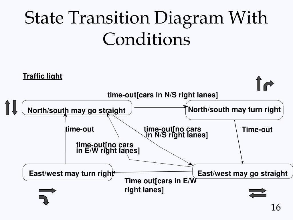
F 21. In a state transition diagram, the states appear as rounded rectangles with the state names inside. T 22. In a state transition diagram, the circle to the left is the final state. F 23. A class diagram resembles a horizontal flowchart that shows the actions and events as they occur. F 24.
In a state transition diagram, the circle at the right with a hollow border is the initial state. False. In a state transition diagram, the circle to the left is the final state. False. In a state transition diagram, the states appear as rounded rectangles with the state names inside.
An alternative, or complementary, way is the use of state transition diagrams. This is the main topic of this chapter. We start in Sect. 13.1 with a brief review of finite state machines and their associated state transition diagrams. We then explain, in Sect. 13.2, how entities can be modeled as state machines, and that in this case state ...
An input alphabet Σ not containing ε. A transition functionset of next states (or successor states). An element s 0 of S, the start state. A subset F of S, the accepting states (or final states). An NFA is basically a flow chart like the transition diagrams we have already seen. Indeed an NFA (or a DFA, to be formally defined soon) can be ...
In a state transition diagram, the circle to the left is the final state. False A class diagram resembles a horizontal flowchart that shows the actions and events as they occur.
Each state diagram must include at least one initial state and one final state (double circle). All sequences must begin with an initial state and continue until they terminate with a final state. The set of states included in a state diagram can be thought of as a one-dimensional attribute space where the single attribute has values, which ...
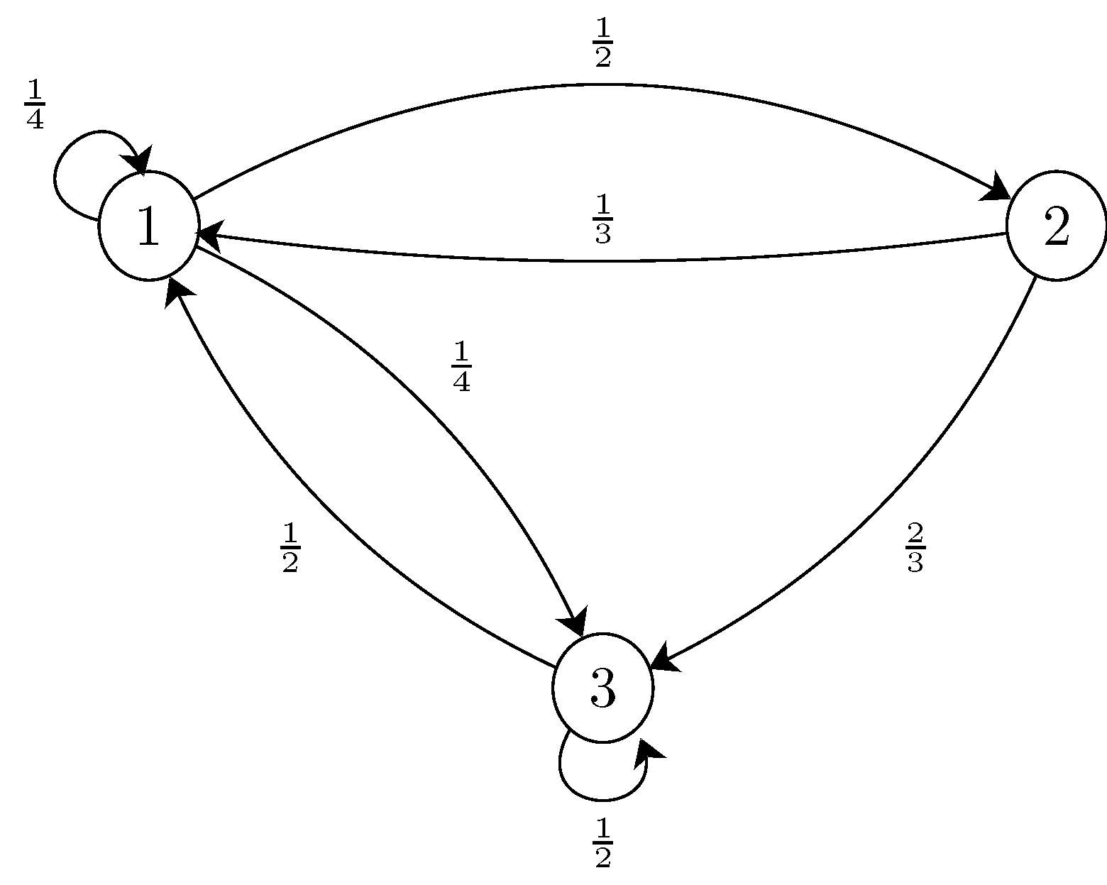
A transition diagram or state transition diagram is a directed graph which can be constructed as follows: There is a node for each state in Q, which is represented by the circle. There is a directed edge from node q to node p labeled a if δ(q, a) = p. In the start state, there is an arrow with no source. Accepting states or final states are ...
Transition state diagram for TR of SEN. (a). Formulation of mathematical model: By applying supplementary variable technique to the assumed ...
For 4 states: State Encoding. S0 00. S1 01. S2 10. S3 11. We need only 2 flipflops to represent these 4 states. For this example we will be using T Flipflips to design the circuit. Let's draw the state transition table using the Excitation table of T flipflop
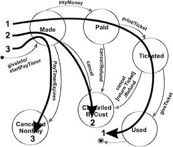
Each state diagram typically begins with a dark circle that indicates the initial state and ends with a bordered circle that denotes the final state. However, despite having clear start and end points, state diagrams are not necessarily the best tool for capturing an overall progression of events. Rather, they illustrate specific kinds of ...
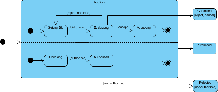
Initial and Final States. The initial state of a state machine diagram, known as an initial pseudo-state, is indicated with a solid circle. A transition from this state will show the first real state The final state of a state machine diagram is shown as concentric circles. An open loop state machine represents an object that may terminate before the system terminates, while a closed loop ...
The state diagram of Mealy state machine is shown in the following figure. In the above figure, there are three states, namely A, B & C. These states are labelled inside the circles & each circle corresponds to one state. Transitions between these states are represented with directed lines. Here, 0 / 0, 1 / 0 & 1 / 1 denotes input / output. In ...
In a state transition diagram, the circle to the left is the final state. diagram. A use case ____ is a visual summary of several related use cases within a ...
Initial and Final States The initial state of a state machine is indicated with a solid circle Known as a pseudo-state A transition from this state will show the first real state The final state of a state machine is shown as concentric circles A closed loop state machine does not have a final state; the object lives until the entire system ...
Initial and Final States. The initial state of a state machine diagram, known as an initial pseudo-state, is indicated with a solid circle. A transition from this state will show the first real state; The final state of a state machine diagram is shown as concentric circles. An open-loop state machine represents an object that may terminate ...
Figure 7.3 shows the state transition diagram for the SITAR system with three redundant COTS servers. Initially, the system is in good state G with no vulnerabilities. Assume that an initial phase of an attack will move the system to the vulnerable state V from state G.During the interval the system is in state V; attackers try various ways to exploit these vulnerabilities in order to cause a ...
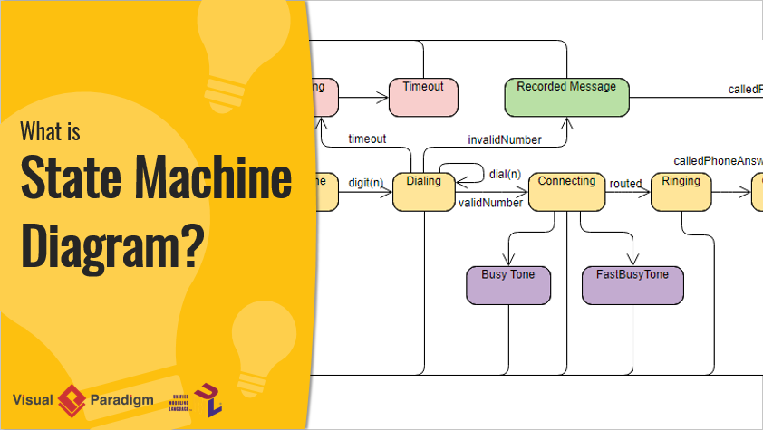
A state diagram is used to represent the condition of the system or part of the system at finite instances of time. It's a behavioral diagram and it represents the behavior using finite state transitions. State diagrams are also referred to as State machines and State-chart Diagrams.These terms are often used interchangeably. So simply, a state diagram is used to model the dynamic behavior ...
State Machine Diagrams. State machine diagram is a behavior diagram which shows discrete behavior of a part of designed system through finite state transitions. State machine diagrams can also be used to express the usage protocol of part of a system. Two kinds of state machines defined in UML 2.4 are . behavioral state machine, and; protocol state machine
Tutorial - 5 Steps to Draw a State Machine Diagram Page 5 of 11 7. Release the mouse button. In the popup pane, select Transit -> Final State. This creates a final state. 8. Click a self-transition on the state account with funds. Move your mouse pointer over the state account with funds and click on the Resource Catalog button. 9.















0 Response to "42 in a state transition diagram, the circle to the left is the final state."
Post a Comment