42 fire alarm tamper switch wiring diagram
d. indicate all fire alarm devices and equipment on plans, wiring diagrams, calcualtions showing secondary supply and voltage drop, and response points. ... fire alarm connection to tamper switch fire alarm connection to flow switch fire alarm relay 3p/60a nema 0 shown size 3-pole, 60 amp, nema 0 rated This functionality makes flow switches an integral part of automated fire alarm systems as they do not require a user to pull down the fire alarm switch. On the other hand, tamper switches try to ensure that human interaction with the fire suppression system, like partial or full closure of the sprinkler system valves, is detected and an alarm ...
Dimension: 2339 x 1654. DOWNLOAD. Wiring Diagram Images Detail: Name: fire alarm flow switch wiring diagram – Water Flow Switch Wiring Diagram Tamper and Flow Switch Wiring Diagrams Lovely Bep2 Od Bioentry. File Type: JPG. Source: magnusrosen.net. Size: 326.83 KB. Dimension: 1032 x 1687.
Fire alarm tamper switch wiring diagram
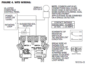
Note: The bottom mounting holes are used to mount the switch on the other side of the cabinet. 3. Set the tamper switch on the screw studs and fa sten the tamper switch to the back box with the two number six flange nuts provided. Figure 1. Tamper Switch Wiring Procedure Refer to Figure 2 and the notes for wiring instructions. Figure 2. A tamper switch is a mechanical and electrical device connected to a fire protection valve that signals a warning if the valve partially or fully closes. Regardless of the type of tamper switch, they all function similarly. The tamper switch features an actuating unit, usually a lever or cable with a resting position. 8 Jun 2021 — The left diagram shows the parts of a tamper switch for an OS&Y valve. ... Some switches sound fire alarms when sprinklers activate.
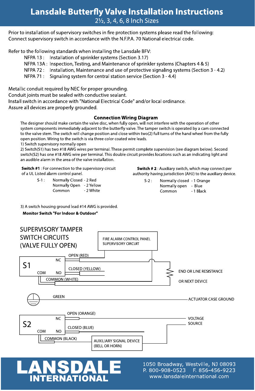
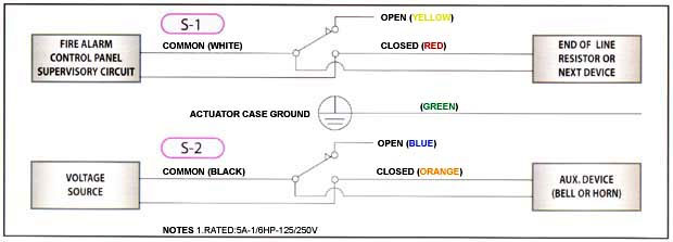
Fire alarm tamper switch wiring diagram. Follow the fire alarm manufacturer's installation sheet exactly. These sheets show the correct wiring. DO NOT USE the labels on the switch inside the tamer ... LISTED FIRE ALARM. CONTROL PANEL. SUPERVISORY CIRCUIT. WIRING DIAGRAM ... NOTE: Valves incorporating supervisory tamper switches are for indoor and outdoor ...1 page Supervisory / tamper switch voltage and current ratings: S.P.S.T. - for valve position supervisory / tamper indication used with U.L. listed fire alarm ... Valve Supervision (Tamper Switch) Selection Guide Fig. ... Four Wire Smoke Detector - A smoke detector which initiates an alarm condition on two separate ...118 pages
The cover tamper switch can be wired into the plug circuit or wired as a separate circuit. (See wiring diagrams.) Testing The PTS-C and its associated protective monitoring system should be tested in accordance with applicable NFPA codes and standards and/or the authority having jurisdiction (manufacturer recommends quarterly or more frequently). Fire Alarm Flow Switch Wiring Diagram. Variety of fire alarm flow switch wiring diagram. A wiring diagram is a streamlined conventional pictorial representation of an electric circuit. It shows the elements of the circuit as simplified shapes, as well as the power as well as signal links between the devices. A wiring diagram normally offers details… Supervisory wiring is the new, common "Use-the-Tamper-Switch-to-Short-Out-the-Wires" method that sends a supervisory alarm to the fire alarm panel when the valve is tampered with. If you determine that it's a Supervisory Tamper, use the diagrams in the manual for the panel. This cover tamper switch mounts to all System Sensor ... National Fire Alarm Code. NFPA 13: ... 1) Wire as required per wiring diagram (Figure 2), placing.2 pages
Fire alarm system is the combination of different components such as smoke detector, heat detector, carbon monoxide detector, multi sensor detector, call points, sounders, bells, relay module, repeater, annunciator, fire control panel and other related and optional security devices designed for fire alarm control system. fire alarm flow switch wiring diagram – Water Flow Switch Wiring Diagram Tamper and Flow Switch Wiring Diagrams Lovely Bep2 Od Bioentry. File Type: JPG. Source: magnusrosen.net. Variety of fire alarm flow switch wiring diagram. Click on the image to enlarge, and then save it to your computer by right clicking on the image. 8 Jun 2021 — The left diagram shows the parts of a tamper switch for an OS&Y valve. ... Some switches sound fire alarms when sprinklers activate. A tamper switch is a mechanical and electrical device connected to a fire protection valve that signals a warning if the valve partially or fully closes. Regardless of the type of tamper switch, they all function similarly. The tamper switch features an actuating unit, usually a lever or cable with a resting position.
1
Note: The bottom mounting holes are used to mount the switch on the other side of the cabinet. 3. Set the tamper switch on the screw studs and fa sten the tamper switch to the back box with the two number six flange nuts provided. Figure 1. Tamper Switch Wiring Procedure Refer to Figure 2 and the notes for wiring instructions. Figure 2.
Potter Pad100 Dim Dual Input Module Tvpn

G Sprinkler Easy Way To Wire Valve Tamper Youtube

Red E Cabinet Dv 5a Installer S Manual
2

Fire By Jules Bartow Technology In The Vein Is It Creepy Or Cool Culture Critic

What Is A Tamper Switch For Fire Protection Systems

Fire Alarm System Wiring Diagram Youtube

Engineering Teknologi Dan Agribisnis 3 Kesalahan Instalasi Smoke Detector Dan Flow Switch
2
07gs3060 Gsm Alarm Communicator User Manual Draft1 29007442r001 Gs3060 V3 0 Im En P65 Digital Security Controls
Fire Protection Technicians Network Fire Alarm Installation And Programming Faq S Page

Potter Tamper Supervisory Switch By Mohannad Faysal Issuu

Fire Alarm Flow Switch Wiring Diagram Blender Kita
Fire Alarm Wiring For More Complete Home Security

Ul Wafer Type Butterfly Valve Z Tide Valve
Fire Alarm
113g3070 Alarm Communicator User Manual Users Manual Digital Security Controls
2
2
2
2

Fire Alarm Flow Switch Wiring Diagram Blender Kita

Fire Alarm System Wiring Diagram 10 Addressable Car Harness New Fire Alarm System Fire Alarm Alarm System

Tamper Switch Connection To The Monitor Module Firealarm Youtube

Model Xr150 Series Wiring Diagram Manualzz
Electrical Basics Of Fire Alarms And Sprinklers

Occupant Evacuation Elevator Code Explained Fire Alarms Online
Lansdale Butterfly Valve Installation Instructions Manualzz

Nx Reliance Installer Manual Cheat Sheet Securefind
Flow Switch And Bell Wiring Electrician Talk

Alarm Pir To Wifi And Home Automation 7 Steps With Pictures Instructables

How To Wire Tamper And Flow Switches Into Fire Alarm
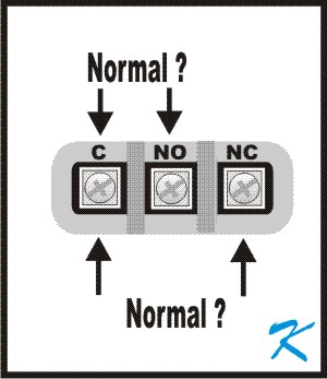
Does The N O Mean Normally Open Or Normally Closed On A Tamper Switch
143g4010 Cellular Alarm Communicator User Manual 29009085r001 3g4010 V4 0 Im Eng Book Digital Security Controls

Instalasi Fire Alarm Konvensional Jogja Safety
Nni Inc Fire Protection Butterfly Valves
2

Fire By Jules Bartow Technology In The Vein Is It Creepy Or Cool Culture Critic
2
Example Dsc Security System Burglar Alarm System

What S The Difference Between A Tamper Switch And A Supervisory Switch
0 Response to "42 fire alarm tamper switch wiring diagram"
Post a Comment