41 shell and tube heat exchanger diagram
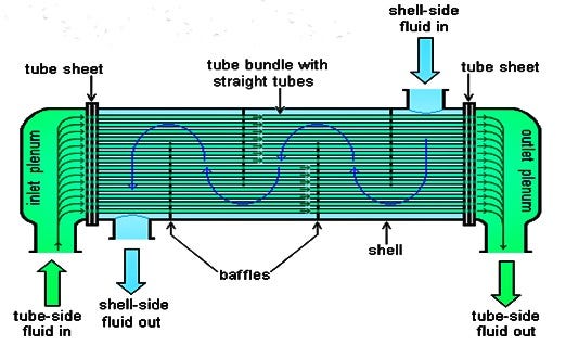
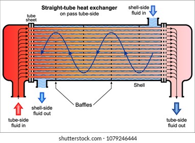
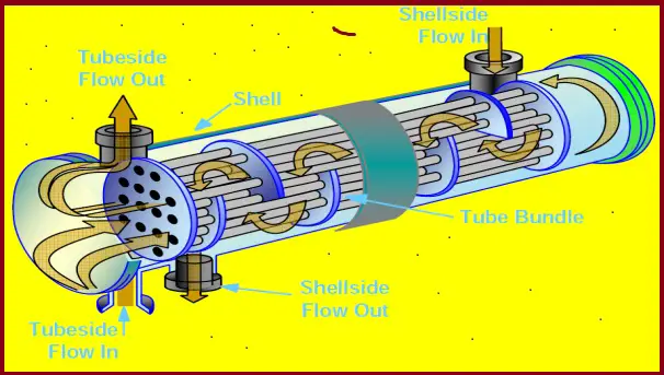
The diagram above shows a Shell and Tube Heat Exchanger. In the counter flow setup, the fluids are travelling along the heat exchanger in opposite directions. On the diagram above the cold fluid, highlighted in blue, is travelling right to left where as the warm fluid, shown in red and amber, travels left to right. This distributes the heat more evenly across the heat exchanger and allows for ... A shell and tube heat exchanger consists of a series of tubes housed within a cylindrical container known as a 'shell'. All tubes within the shell are ...
The working of a shell and tube heat exchanger is fairly simple. One fluid flows inside the tubes and the other through the shell. While flowing they exchange ...
Shell and tube heat exchanger diagram
The plant consists, typically, of an inclined rotating shell with a tube heat exchanger (see Fig. 11.3). The shell is heated by low-pressure (waste) steam at 0.4–0.5 MPa and at … 01/06/2018 · Schematic diagram of heat wheel . ... other advantage plate heat exchangers offer in comparison with similar types of heat exchanger such as the conventional shell and tube heat exchangers is the fact the hot and cold fluids are exposed to a larger surface area per unit volume and a larger heat transfer coefficient . It is reported that there are mainly three types of plate heat exchanger ... Heat Exchanger Design Handbook. Matt Pennington. Download PDF. Download Full PDF Package. This paper. A short summary of this paper. 19 Full PDFs related to this paper. Read Paper. Heat Exchanger Design Handbook. Download ...
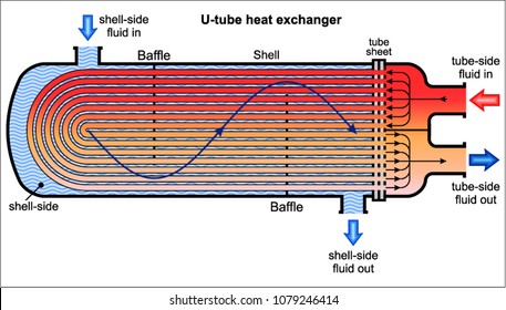
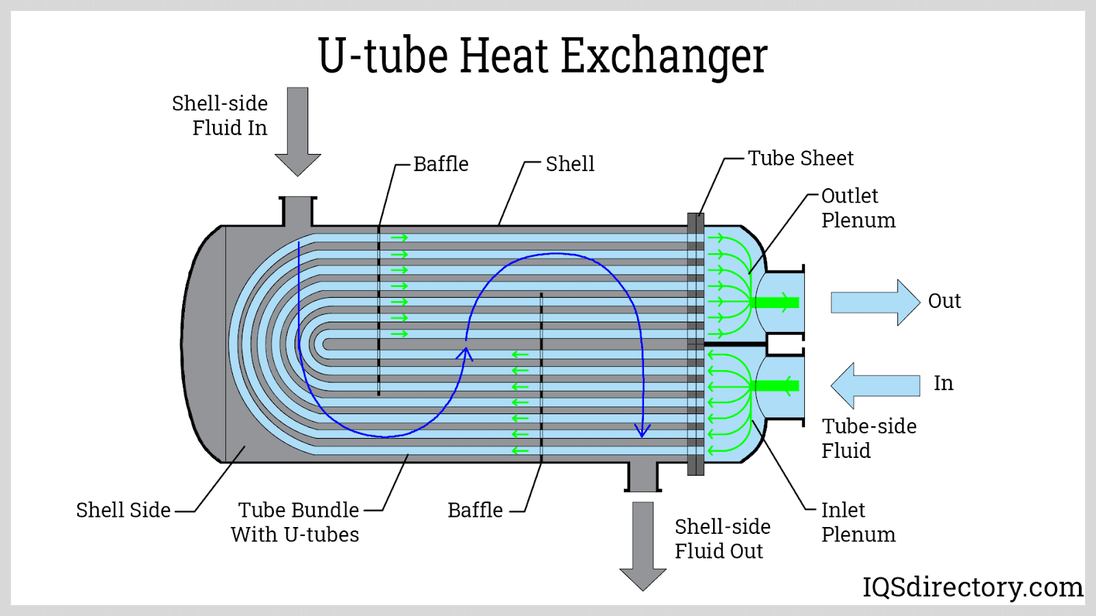
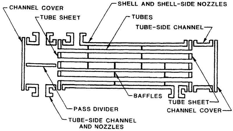
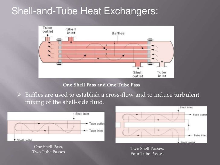
Shell and tube heat exchanger diagram. In the shell and tube heat exchanger process, one fluid flows through the tubes while the other fluid flows through the shell. In the diagram below, which is of ... This type of heat exchangers consists of metal tubes passing through another metal enclosure, which is referred to as the 'shell'. So typically we have a fluid ... Figure 5.18 Schematic of one-shell one-pass (1-1) shell-and-tube heat exchanger. Baffles. In Figure 5.18, baffles are placed within the shell of the heat ...17 pages A shell and tube exchanger consists of a number of tubes mounted inside a cylindrical shell. Figure 1 illustrates a typical unit that may be found in a ...Fixed tubesheet exchangers: U-tube exchang...AEM: CEUAEL: AEUAEN: DEU
14/07/2005 · With shell-in tube heat exchangers , as shown in figure 4, the tube may be coiled inside a large shell, with product also flowing through the tube in a direction opposite to the flow of heating ... Shell and tube heat exchangers are, simply put, a device that puts two working fluids in thermal contact using tubes housed within an outer cylindrical shell. As its name implies, this type of heat exchanger consists of a shell (a large pressure vessel) with a bundle of tubes inside it. One fluid runs through the ...Shell and tube heat exchanger... · Selection of tube material · Applications and uses Heat Exchanger Design Handbook. Matt Pennington. Download PDF. Download Full PDF Package. This paper. A short summary of this paper. 19 Full PDFs related to this paper. Read Paper. Heat Exchanger Design Handbook. Download ...
01/06/2018 · Schematic diagram of heat wheel . ... other advantage plate heat exchangers offer in comparison with similar types of heat exchanger such as the conventional shell and tube heat exchangers is the fact the hot and cold fluids are exposed to a larger surface area per unit volume and a larger heat transfer coefficient . It is reported that there are mainly three types of plate heat exchanger ... The plant consists, typically, of an inclined rotating shell with a tube heat exchanger (see Fig. 11.3). The shell is heated by low-pressure (waste) steam at 0.4–0.5 MPa and at …
Floating Head

Hexoloy Shell Tube Exchangers Faq
2

Vector Illustration Shell And Tube Heat Exchanger Stock Clip Art Gg75884687 Gograph
Shell Tube Type Heat Exchangers Air Preheater By Thermodyne Boilers Medium
Shell And Tube Heat Exchanger Images Stock Photos Vectors Shutterstock

Plate Heat Exchanger Shell Dan Tube Heat Exchanger Reboiler Gas Alam Pemisahan Alami Sudut Teks Pendinginan Png Pngwing

Shell And Tube Heat Exchanger Structure Concept Download Scientific Diagram

Multipass Shell Dan Tube Heat Exchanger Produsen Dan Pemasok Harga Grosir Wuxi Tecfree
Shell And Tube Heat Exchanger What Is It Types Process
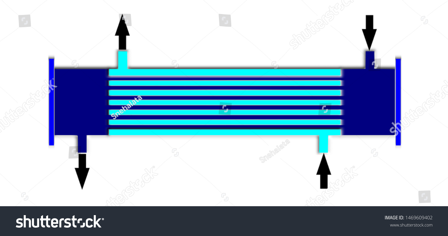
Ilustrasi Stok Shell Tube Heat Exchanger Diagram 1469609402

What Dominates Heat Transfer Performance Of Hybrid Nanofluid In Single Pass Shell And Tube Heat Exchanger Sciencedirect
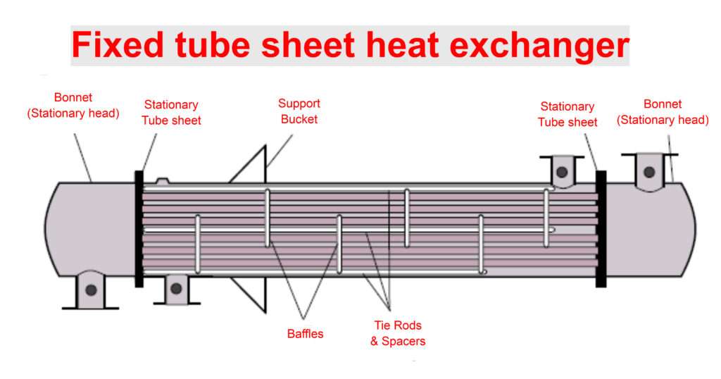
Fixed Tube Sheet Heat Exchanger Chemical Engineering World
5 1 Shell And Tube Heat Exchangers

Ert 209 Heat And Mass Transfer For Bioprocess

Structural Detailed Solution Of Shell And Tube Heat Exchanger Metal Oil Gas News

Shell And Tube Heat Exchanger Piping And Instrumentation Diagram Pipe Pipe Angle Text Rectangle Png Pngwing
Shell And Tube Heat Exchanger Images Stock Photos Vectors Shutterstock

Heat Transfer By Shell And Tube Heat Exchangers

Studies On Application Of Solarwater Heating System Assisted Shell And Tube Heat Exchanger For Pasteurization Of Milk Semantic Scholar

Design Of Multiple Shell And Tube Heat Exchangers In Series E Shell And F Shell Sciencedirect

Shell And Tube Heat Exchangers

Shell Tube Heat Exchangers Shell Tube Heat Exchanger Tube Shell Heat Exchanger Shell Heat Exchanger

Shell And Tube Heat Exchanger

Shell Tube Heat Exchanger For Ticc Edibon
Heat Transfer By Shell And Tube Heat Exchangers Tema Designations Of Heat Exchangers

Shell And Tube Heat Exchanger Wikipedia

Shell Tube Heat Exchangers Piping Layout Part 1 Piping Mantra Youtube

Volume Xxiii Components Of Shell Tube Heat Exchangers Boardman Llc

Shell Tube Heat Exchanger Animation Youtube
Introduction Heat Exchanger Design Handbook Multimedia Edition
New Shell Tube Heat Exchanger

Macam Macam Heat Exchanger Alat Penukar Panas Bagian 2 Artikel Teknologi Indonesia

Scielo Brasil Thermal Performance Of One Pass Shell And Tube Heat Exchangers In Counter Flow Thermal Performance Of One Pass Shell And Tube Heat Exchangers In Counter Flow

Shell And Tube Type Heat Exchanger Explained Savree

Shell Tube Heat Exchanger Diagram Enggcyclopedia

Typical Shell Tube Heat Exchanger P Id Diagram Enggcyclopedia

Schematic Diagram Of Shell And Tube Heat Exchanger 1 Download Scientific Diagram
Basics Of Shell And Tube Heat Exchangers With Pdf What Is Piping

Design And Economic Investigation Of Shell And Tube Heat Exchangers Using Improved Intelligent Tuned Harmony Search Algorithm Sciencedirect

A Shell And Tube Heat Exchanger With One Shell Pass And One Tube Pass Download Scientific Diagram
0 Response to "41 shell and tube heat exchanger diagram"
Post a Comment