41 draw a ray diagram of the lens system in part d
A real image is an image that can be projected onto a screen. A virtual image appears to come from behind the lens. To draw a ray diagram: Draw a ray from the object to the lens that is parallel ... Jul 22, 2021 · (c) a lens holder, a screen holder and a scale. (d) a convex lens, a screen, holders for them and a scale. Question 5: After performing the experiment to determine focal length of a convex lens by focussing a distant object, a teacher asked Asha to draw a j ray diagram of her experiment and show where did she place the screen for getting sharp ...
Lenses Ray Diagram Construction Worksheet Teaching. Long Answer Questions 30. On the diagram, label the point on the mirror where the incident ray from A reflects from the mirror with the letter "x". Draw a scale ray diagram showing the image position and height. Draw a ray diagram for a convex mirror when an object is placed at 2F.

Draw a ray diagram of the lens system in part d
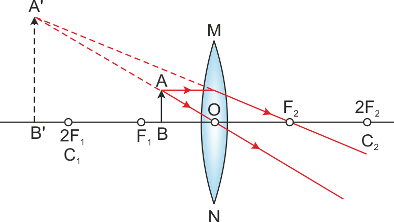
12. (a) In the space below, draw a ray diagram for a Cassegrain reflecting telescope. Your diagram should show the paths of two rays from a distant object, which pass through the telescope and emerge from the eyepiece lens. (3) (b) (i) With the aid of a ray diagram, explain what is meant by spherical aberration of a curved mirror. First, we draw a ray parallel to principal axis. So, it appears to pass through focus after reflection. We draw another ray which passes through Optical Center. So, the ray will go through without any deviation. Where both reflected rays meet is point A'. And the image formed is A'B'. This image is formed between F 1 and Optical Center (O) We ... Nov 21, 2021 · Draw center points on each edge (Hint: to find the center point, draw diagonals to each corner. Remember, you can draw just about anything in perspective by first drawing the 'box it came in'. Have the cut-outs big or small, front or back. e. The main line is a vertical line that is in a corner of the frontal part. Have fun !
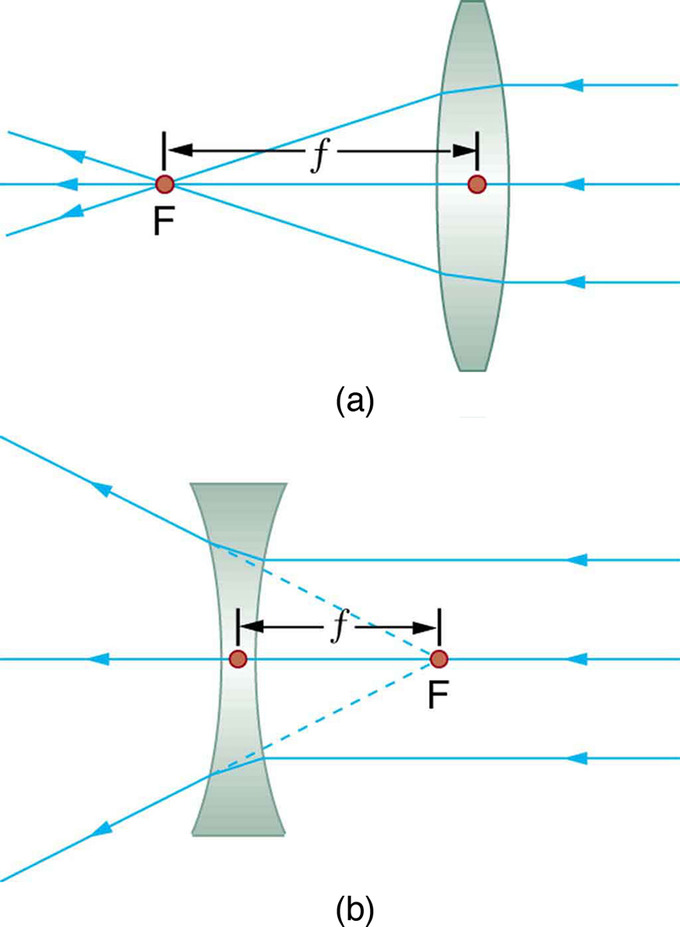
Draw a ray diagram of the lens system in part d. A cathode-ray tube (CRT) is a vacuum tube containing one or more electron guns, the beams of which are manipulated to display images on a phosphorescent screen. The images may represent electrical waveforms (oscilloscope), pictures (television set, computer monitor), radar targets, or other phenomena. A CRT on a television set is commonly called a picture tube. Advanced Physics questions and answers. 10. Draw a ray diagram for Method I. Use at least two rays. (8 pts) 11. Draw a ray diagram for Method II. Use at least two rays. (8 pts) Part 2: Diverging Lens to determine the focal length of a diverging lens, the ens must create a measurable, real image as in Part 1.. Convergin nh. Ray Diagrams for Lenses. The image formed by a single lens can be located and sized with three principal rays. Examples are given for converging and diverging lenses and for the cases where the object is inside and outside the principal focal length. Part of the light reflected from the bottom surface can emerge from the top of the film (ray 2) and interfere with light reflected from the top (ray 1). Since the ray that enters the film travels a greater distance, it may be in or out of phase with the ray reflected from the top. However, consider for a moment, again, the bubbles in Figure 1.
Yet the same method works for drawing a ray diagram for any object location. 1. Pick a point on the top of the object and draw two incident rays traveling towards the mirror. Using a straight edge, accurately draw one ray so that it passes exactly through the focal point on the way to the mirror. Draw the second ray such that it travels exactly ... In each of these two example problems, the angle of refraction is the variable to be determined. The indices of refraction (n i and n r) are given and the angle of incidence can be measured.With three of the four variables known, substitution into Snell's law followed by … Ray diagrams for convex mirrors answer key. Ray diagrams for convex mirrors answer key ... Step-by-Step Method for Drawing Ray Diagrams. The method of drawing ray diagrams for double convex lens is described below. The description is applied to the task of drawing a ray diagram for an object located beyond the 2F point of a double convex lens. 1. Pick a point on the top of the object and draw three incident rays traveling towards the ...
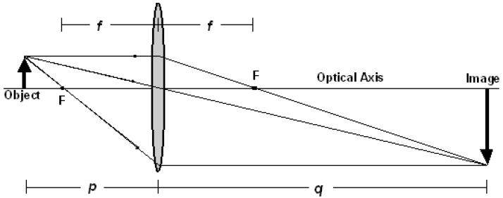
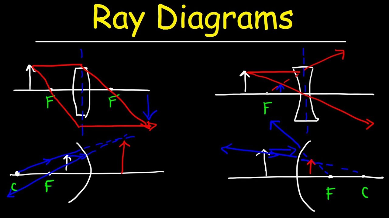
Part D . Converging Lens Example. In order to illustrate the method of drawing a ray diagram for a converging lens, we will consider the situation in which a real object is placed to the left of a converging lens. The bottom of the object will sit on the optical axis, and the top of the object will sit above the optical axis. ... a) Draw a ray diagram of the experiment conducted in part C (determining your blinds spot) only include rays that travel straight from the laser on the board to your eye b) Draw a ray diagram of the lens system in part D; Question: Please help! I am not good a drawing ray diagrams, and I would like to double check what I did to make sure its right. Diagram of periscope Meade telescope parts diagram. The second piece is a spacer. Thanks for the help! 1- The Tube assembly: This is the long white part and it holds the mirror, the secondary mirror, the …
Ray Diagram For A Combination Of Two Lenses Blue Disks With Variable Download Scientific Diagram
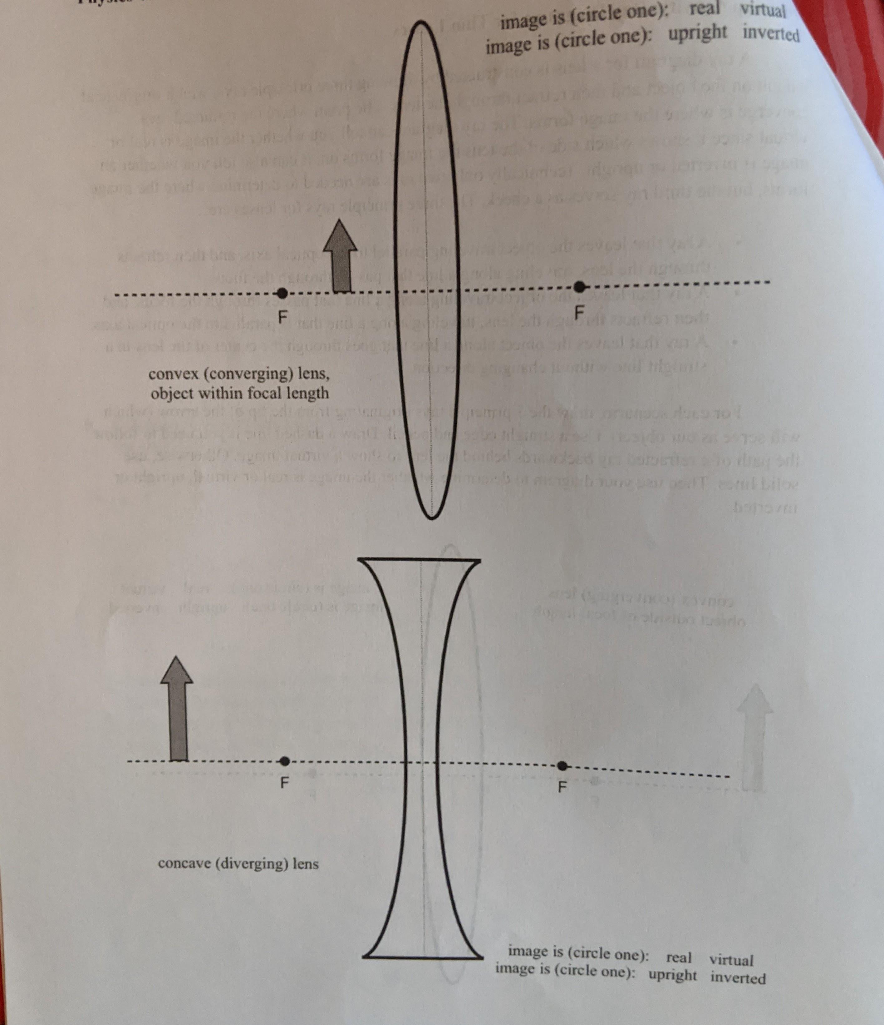
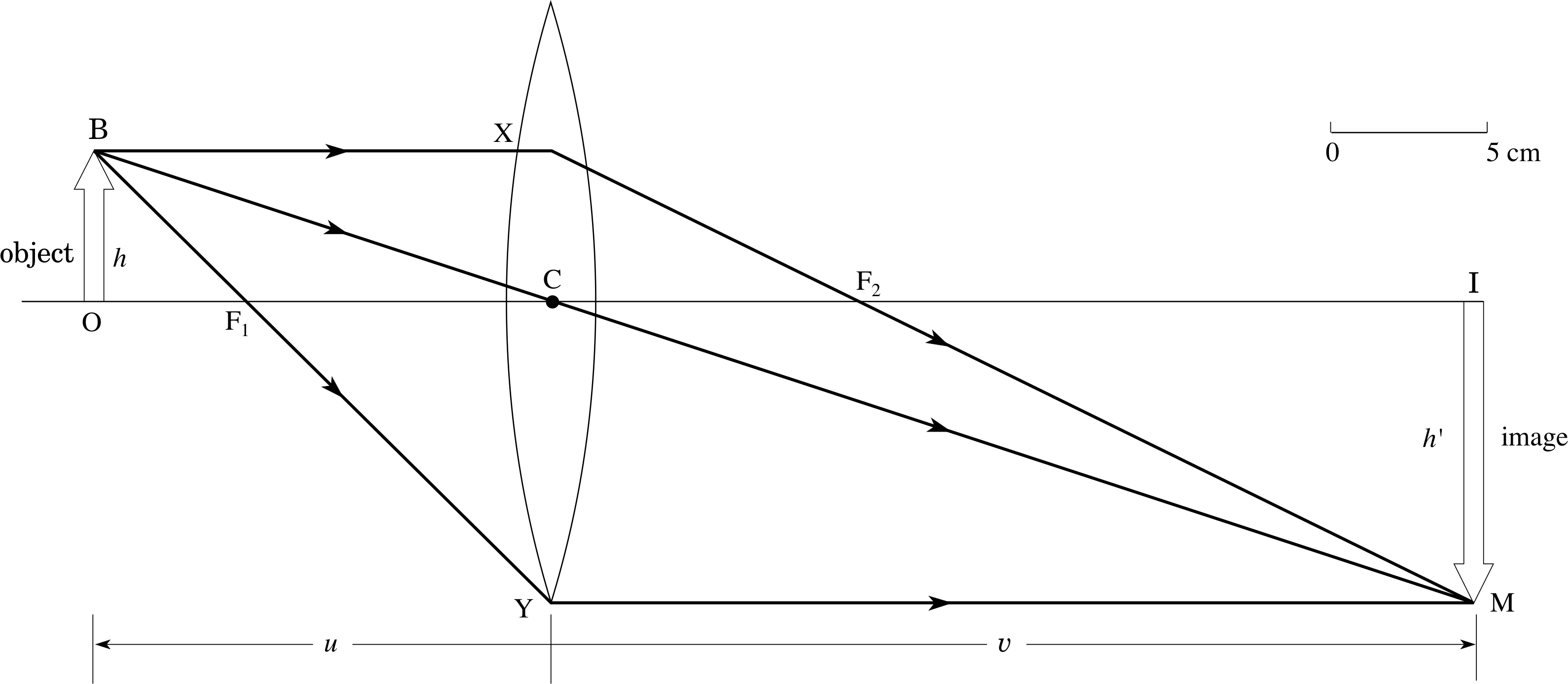
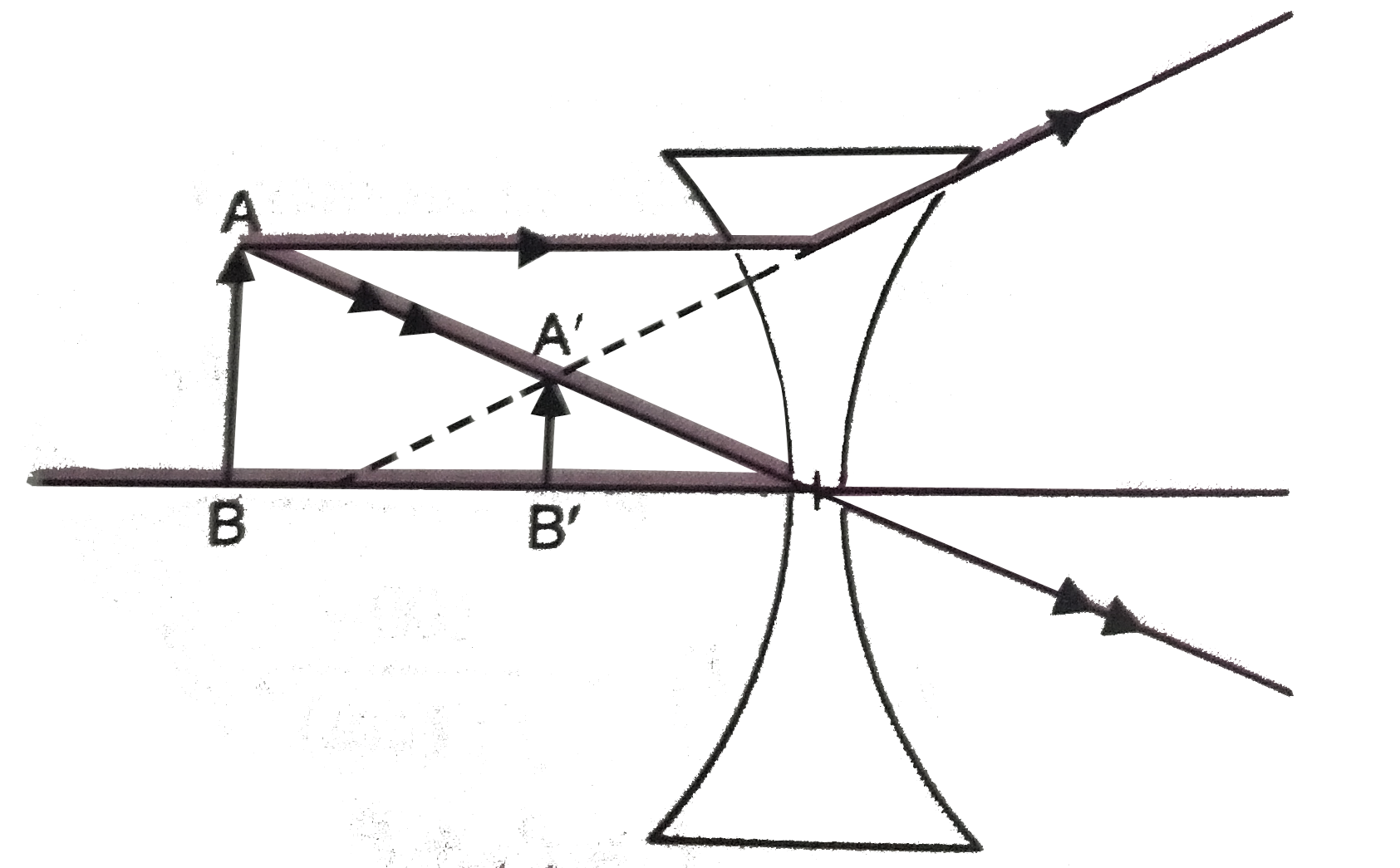
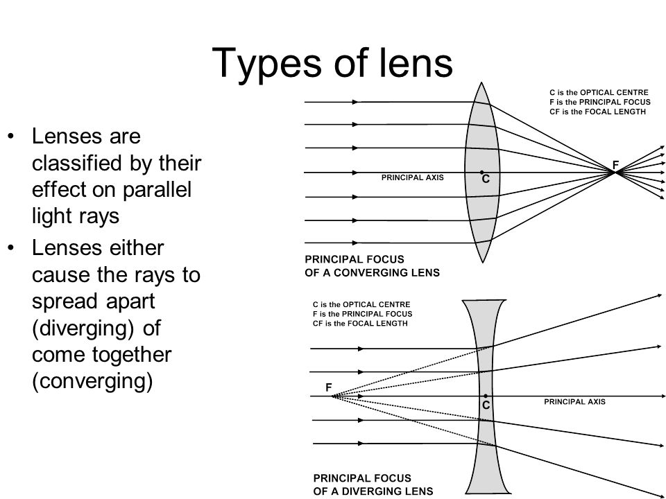
For aconvex lens, we draw the ray diagram as follows: Draw a ray from the top of the object straight through the middle of the lens. Its direction is not changed. Draw a ray from the top of the object parallel to the principal axis. It is refracted by the lens to pass through the focal point. F From the diagram we see that the image in this ...
Draw A Ray Diagram In Each Of The Following Cases To Show The Formation Of Image When The Object Is Placed I Between Optical Centre And Principal Focu Physics Topperlearning Com
The largest part is the main body (barrel) of the eyepiece itself. 4") Altazimuth Refracting Telescope Instruction Manual 70AZ-ADR Mar 15, 2012 · ETX 125 parts list and diagram - posted in Meade Computerized Telescopes: I bought a 125 online and when I received it, the Ra motor and gear drive worked but the gear spun on the shaft.
Thin Lenses And Lens Systems
Nov 21, 2021 · Draw center points on each edge (Hint: to find the center point, draw diagonals to each corner. Remember, you can draw just about anything in perspective by first drawing the 'box it came in'. Have the cut-outs big or small, front or back. e. The main line is a vertical line that is in a corner of the frontal part. Have fun !
Draw A Ray Diagram Representing Your Experiment From Part C Wiring Site Resource
First, we draw a ray parallel to principal axis. So, it appears to pass through focus after reflection. We draw another ray which passes through Optical Center. So, the ray will go through without any deviation. Where both reflected rays meet is point A'. And the image formed is A'B'. This image is formed between F 1 and Optical Center (O) We ...
Lenses Boundless Physics
12. (a) In the space below, draw a ray diagram for a Cassegrain reflecting telescope. Your diagram should show the paths of two rays from a distant object, which pass through the telescope and emerge from the eyepiece lens. (3) (b) (i) With the aid of a ray diagram, explain what is meant by spherical aberration of a curved mirror.

16 3 Lenses Texas Gateway
Solved Followup Activity Ray Diagrams For Thin Lenses A Ray Chegg Com
Day 27 Drawing Ray Diagrams Lenses Mrcampbellsscienceclass
Pplato Flap Phys 6 3 Optical Elements Prisms Lenses And Spherical Mirrors
2

Lab 5 Lenses And Ray Diagrams Pdf Scu Physics 32 Summer 2020 Name Lab Partners Lab 5 Lenses And Ray Diagrams Introduction Lenses Come In Many Course Hero
Ray Diagrams For Lenses
Lenses Boundless Physics

Drawing Ray Diagrams For A Converging Lens The Fizzics Organization
Physics Tutorial Refraction And The Ray Model Of Light
Physics Tutorial Refraction And The Ray Model Of Light
Please Help I Am Not Good A Drawing Ray Diagrams Chegg Com
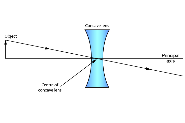
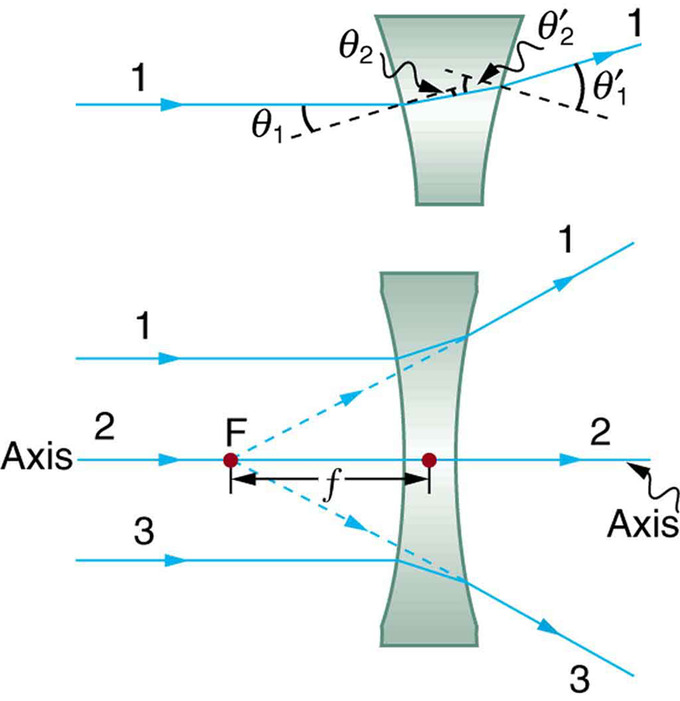
Method For Drawing Ray Diagrams Concave Lens

Draw Ray Diagram Showing The Image Formation By A Convex Lens When An Object Is Placed At Infinity
If The Image Formed By A Lens For All Positions Of An Object Placed In Front Of It Is Always Erect And Diminished What Is The Nature Of This Lens Draw

Ray Diagrams For Lenses Light Science Physics Diagram
1
Solved A Draw A Ray Diagram Of The Lens System As It Should Look At The End Of Step C6 The Setup For Forming The Image Of A Real Image Draw The Ray

Draw Ray Diagrams To Represent The Nature Position And Relative Size Of The Image Formed By A Convex Brainly In

Draw A Ray Diagram Representing Your Experiment From Part C Wiring Site Resource
Draw A Ray Diagram Representing Your Experiment From Part C Wiring Site Resource
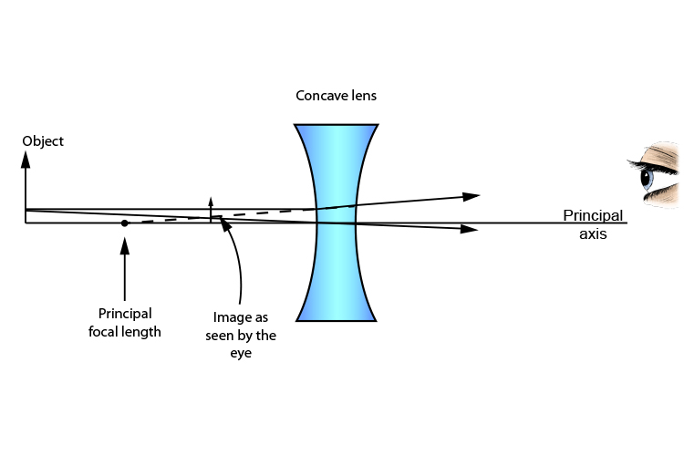
Method For Drawing Ray Diagrams Concave Lens

Drawing Ray Diagrams For A Converging Lens The Fizzics Organization
Lab 9 Ray Diagrams
Physics Tutorial Refraction And The Ray Model Of Light

Different Lens Ray Diagram Questions Evan S Space
Draw A Ray Diagram Representing Your Experiment From Part C Wiring Site Resource
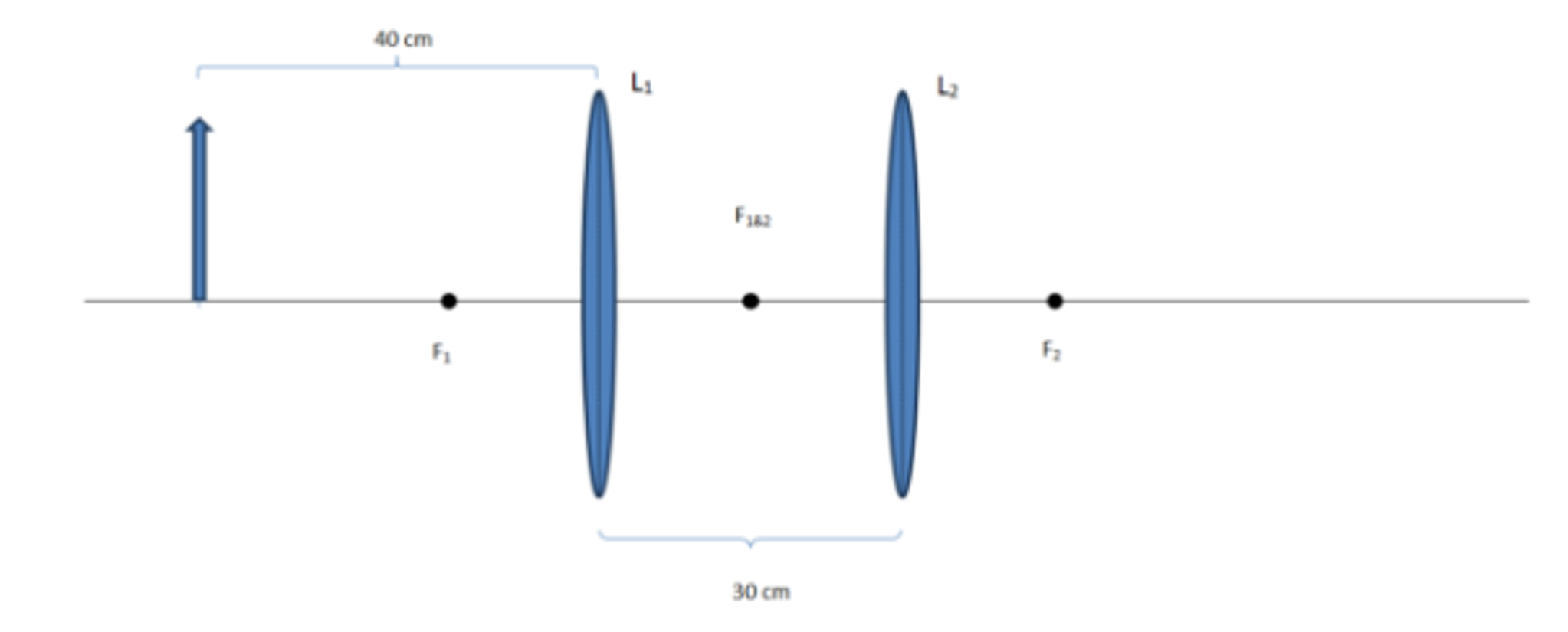
Solved Construct A Ray Diagram For The Two Lens System Chegg Com

A Draw A Ray Diagram To Show The Formation Of An Image By A Convex Lens When An Object Is Placed In Front Of The Lens Between Its Optical Centre And Principal
2
Ray Diagrams For Lenses

Which Of The Following Ray Diagrams Is Correct For The Ray Of Light Incident On A Lens Shown In Fig 10 7
Waves Drawing Ray Diagrams For Converging Lenses Ppt Download

Draw A Ray Diagram Representing Your Experiment From Part C Wiring Site Resource

How To Draw A Converging Lens Light Ray Diagram Youtube
Ray Diagrams Youtube
0 Response to "41 draw a ray diagram of the lens system in part d"
Post a Comment