41 4 position rotary switch wiring diagram
26-02-2014 · View and Download JLG 600SJ service and maintenance manual online. 600SJ boom lifts pdf manual download. Also for: 600s, 660sj. 4. Testing. It is very important that wiring be connected according to the diagram. The hot lines and neutral from each source must be identified and.
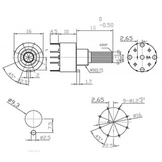
Measured in degrees, the angular distance between positions determines the number of switch positions. For example, a 4-position rotary switch has a 90° angle ...
4 position rotary switch wiring diagram
28 Apr 2015 — Most of what I'm finding online is tutorials for rotary-encoders, ... Attached is a diagram of a six position rotary switch I had connected ... 'pole' - hence the name 3 pole 4 way. Fig. 1a A typical Rotary Switch. Fig. 1b Circuit diagram for one pole of a 3 pole 4 way switch.2 pages Wiring Diagram Trailer Plugs and Sockets. Narva 7 and 12 pin trailer connectors comply with all relevant ADRs. Flat connectors comply with Australian Standards AS4177.5-2004. Large and small round connectors comply with AS2513-1982 while Heavy duty connectors meet the AS4735-2003 standard as required for vehicles and trailers over 3.5 tonnes.
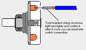
4 position rotary switch wiring diagram. 20-10-2019 · Hi I need help I’m trying to build a pop-up target with ESP32/esp8266 boards And servo motor and button/switch. This is what I’m trying to build. When the target is hit it will fall and hit the switch and it will restart servo motor to go up 180 degrees Back to 0 Degrees I’m new at this and I have been working on this for About year. 3-way and 6-position rotary switch guitars - for selecting different tones and effects ... The following is a guide to basic rotary switch wiring:. Electrical Contactor: The purpose of the contactor is to switch ON/OFF the power supply to the motor by making or breaking the contact terminals.; Overload protection circuit: The purpose of this circuit is to protect the motor from potential harm due to the overload condition.Huge current through the rotor may damage the winding as well as other appliances connected to the supply. 2 Single Coils: 2 Tele Single Coils/3-Way Lever Switch/1 Volume/1 Tone-Typical Fender Telecaster Wiring; 2 Tele Single Coils/4-Way Lever Switch/1 Volume/1 Tone-Telecaster w/ 4-Way Mod Switch to Add Neck+Bridge Series Option2 J-Bass Single Coils/2 Volumes/1 Tone-Typical Fender Jazz Bass Wiring; 2 J-Bass Single Coils/Blend Pot/1 Volumes/1 Tone-Jazz Bass w/ Master Volume & …
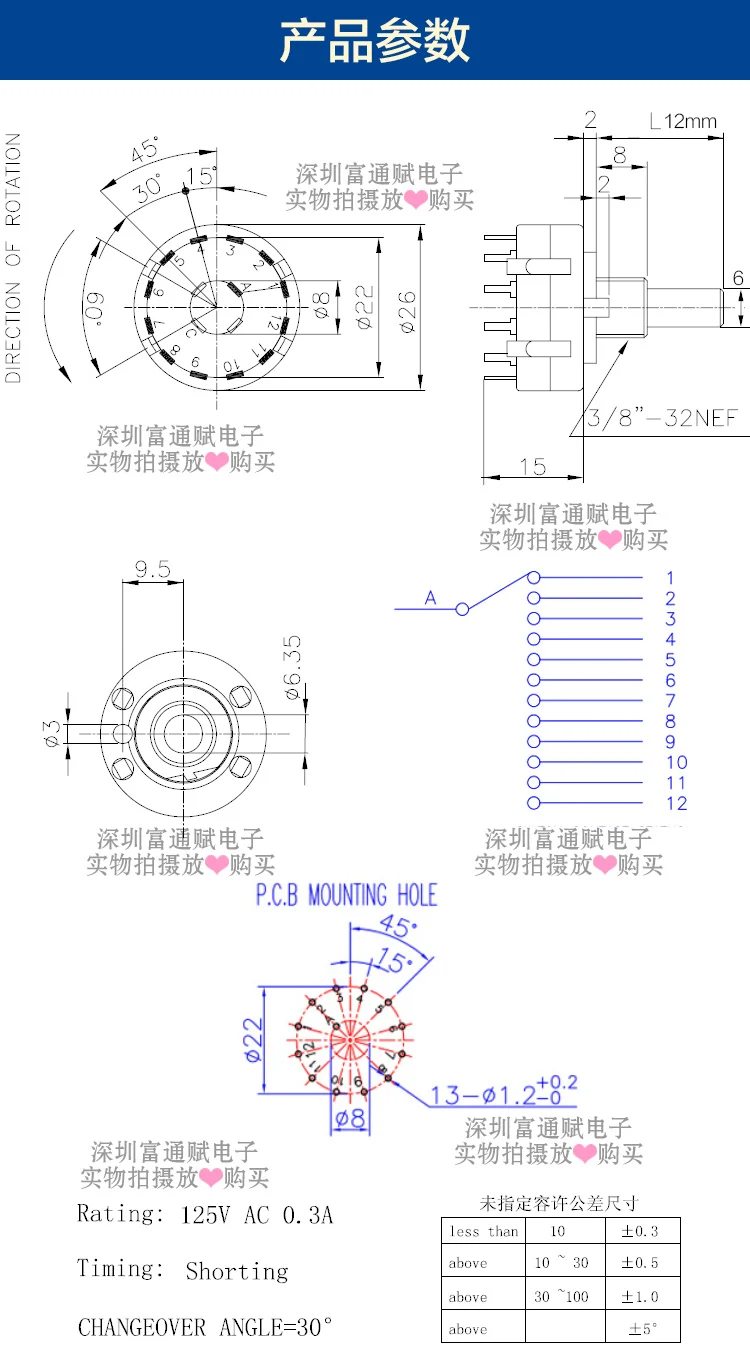
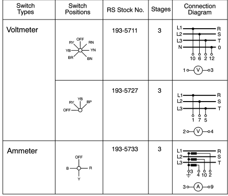
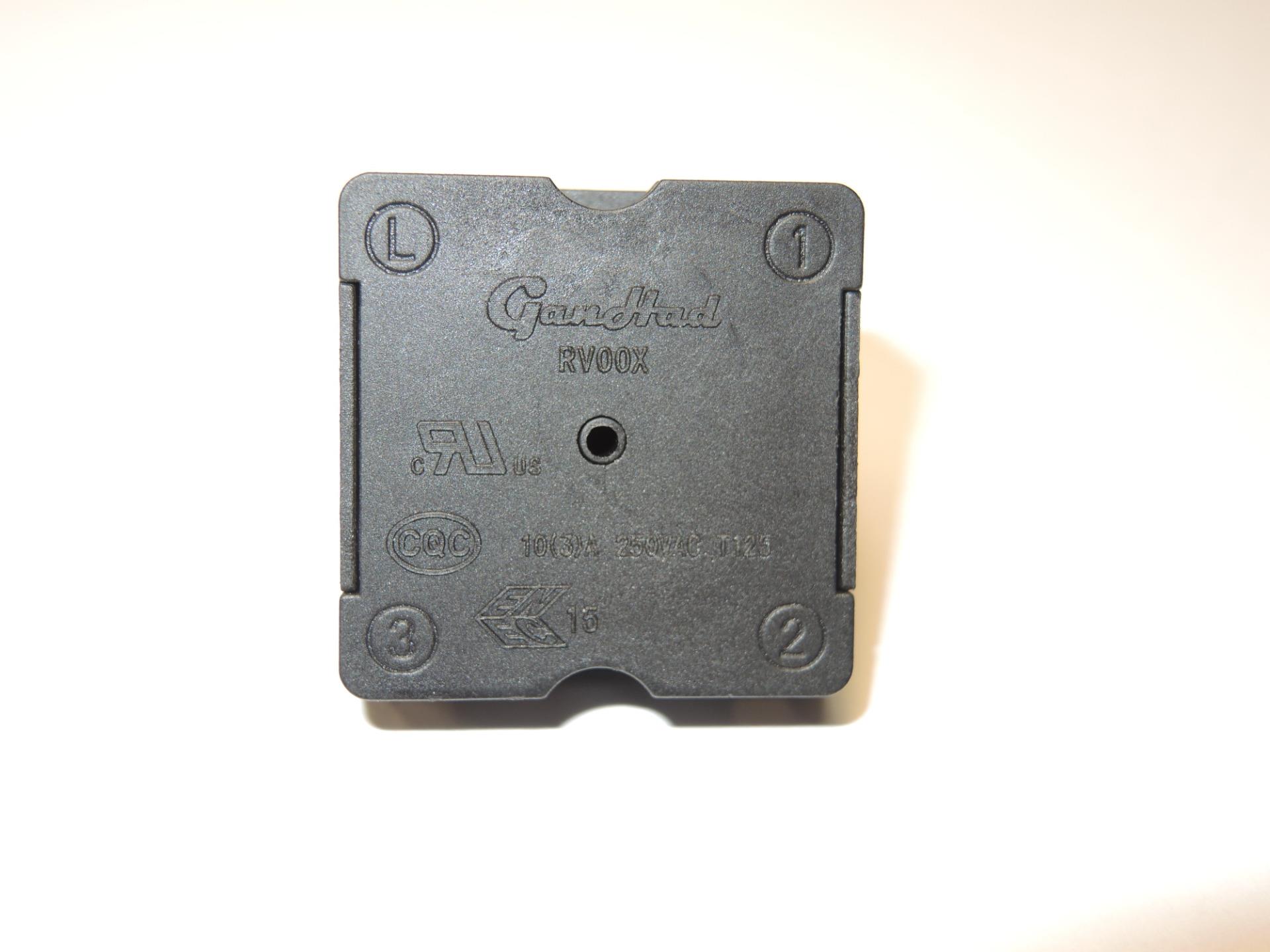
Schematic diagram. Wiring diagram. Installation diagram. 2 - CONSTITUTION OF THE DIAGRAMS: ... steering wheel rotary connector. CV00: switch unit under steering wheel (СОМ 2000). DRAG: shielded earth. ... selector lever position switch. 1601: one-touch control lever sensor. 1602: ... For example, contact 3/4 closes in the delta position. A vertical line between 2 or more crosses indicate that the contact remains closed while the switch moves ...92 pages 07-02-2021 · Rotary switch in a closed position Rotary Open Switch Rotary Switch in the open position. NO Push Button ... 4 position switch manual switch pushbutton make switch pushbutton ... EdrawMax is one of the top-selling wiring diagram makers that helps you create diagrams, ... In order for the PLC program to work properly with this new switch wiring, the virtual contact for IN_switch_Stop must be changed from a normally-closed (NC) to a normally-open ... The following example shows a wiring diagram, ... Numbered tabs on the circumference of the drum mark the drum’s rotary position in one of 24 increments.
20 Jul 2019 — Hi folks, Looking for a wiring diagram for a simple rotary switch. Available wires are white, blue and black. Thanks for any suggestions you ... Wiring Diagram Trailer Plugs and Sockets. Narva 7 and 12 pin trailer connectors comply with all relevant ADRs. Flat connectors comply with Australian Standards AS4177.5-2004. Large and small round connectors comply with AS2513-1982 while Heavy duty connectors meet the AS4735-2003 standard as required for vehicles and trailers over 3.5 tonnes. 'pole' - hence the name 3 pole 4 way. Fig. 1a A typical Rotary Switch. Fig. 1b Circuit diagram for one pole of a 3 pole 4 way switch.2 pages 28 Apr 2015 — Most of what I'm finding online is tutorials for rotary-encoders, ... Attached is a diagram of a six position rotary switch I had connected ...
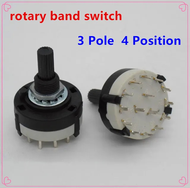
Help Wiring P J With A 4 Position 3 Pole Rotary Switch Talkbass Com
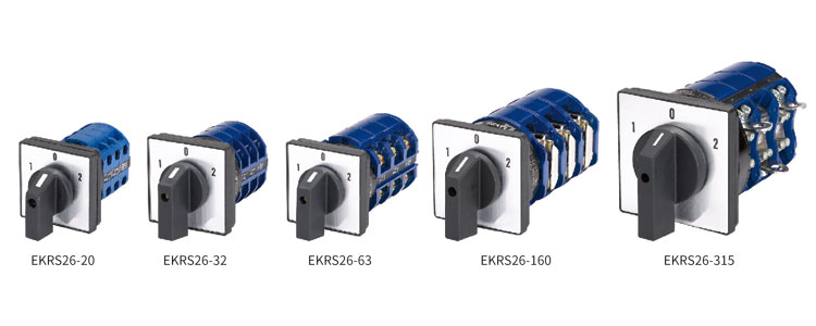
Electrical Rotary Switches 3 Positions Rotary Switches Rotary Switch Ekrs26 China Zhejiang Etek Electrical

3 Position Rotary Switch The Gear Page
0499000074 4 Position Rotary Switch With Hard Wire Push In Connections

Help Required In Wiring A Four Position Rotary Switch Electrics Non Dcc Rmweb

Guitar Cartoon Png Download 998 827 Free Transparent Rotary Switch Png Download Cleanpng Kisspng

3 Pole 4 Position Rotary Switch For H H Guitar Help Please Seymour Duncan User Group Forums
Two Circuit Rotary Switch 40402i B P Lamp Supply
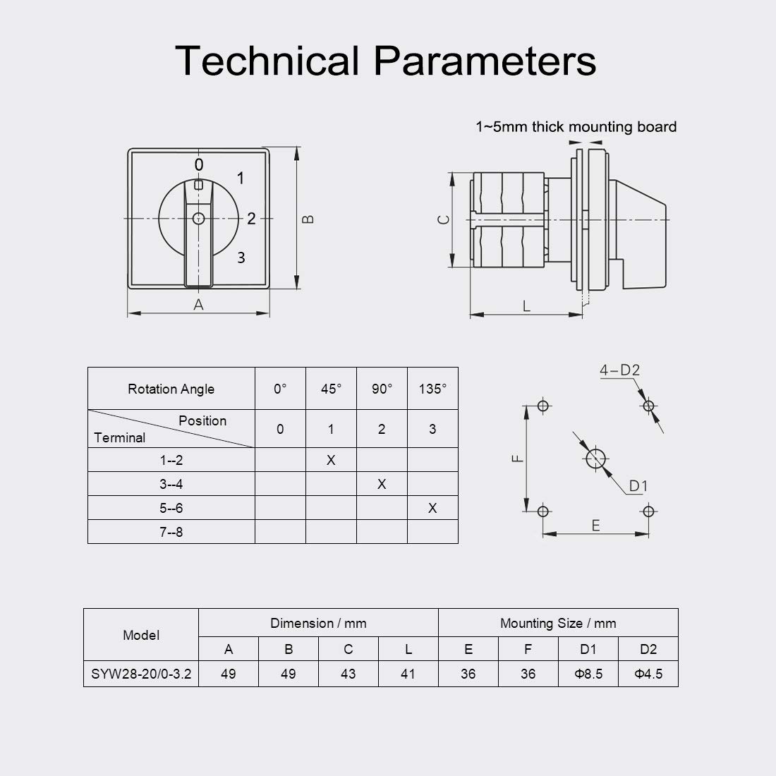
Buy Victorshome Changeover Switch Syw28 20 4 Positions 8 Terminals Universal Rotary Cam Selector Latching Switches 550v 20a Online In Japan B07mz6y7y9
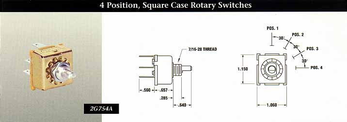
4 Position Square Case Rotary Switches Indak Switches
2pcs High Quality Rs26 3 Pole Position 4 Selectable Band Rotary Channel Selector Switch Single Deck Rotary Switch Band Selector Selector Switch Selector Rotary Switch Aliexpress
10 Pcs 4 Pole 3 Posisi Panel Custom Wiring Rotary Switch 4p3t Wiring 3 Way Light Switch Wire Bathroomswitch Tool Aliexpress

Rotary 4 Pole Wiring Diagram Diagram Base Website Wiring

Buy Rotary Switch 4 Position 3 Speed 13a 125v 10a 250v Fan Heater Speed Selector 2pcs Type A Online In Indonesia B08p52htpy
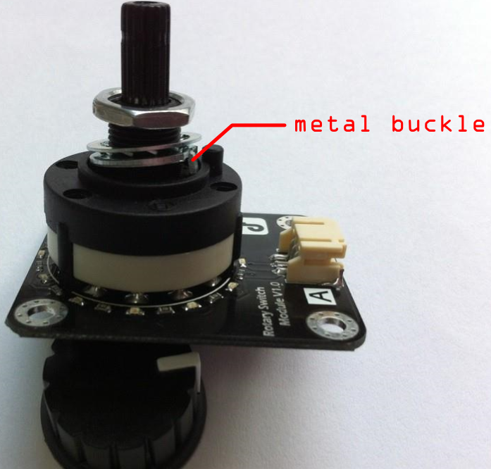
Rotary Switch Module V1 Sku Sen0156 Dfrobot

Rotary Switch Wiring The Gear Page

Blue Sea Systems Ac Source Selection Rotary Switch Panels West Marine

12a Pulse 2 To 8 Speed Rotary Switch Used For Blender Juicer Coffee Machine China Rotary Switch Switch Made In China Com

Help Required In Wiring A Four Position Rotary Switch Electrics Non Dcc Rmweb

How To Wire Up A 4 Way Rotary Switch General Electronics Arduino Forum
Gibson Eb3 4 Position Rotary Switch Wiring Diagrams Talkbass Com

Beavis Audio Research

How Does This 2 Poles Rotary Switch Work General Electronics Arduino Forum
Info Ee Surrey Ac Uk

Rotary Cam Changeover Switch 6 Terminals 4 Positions Youtube
1 Pcs 4 Pole 2 Posisi Panel Custom Wiring Rotary Switch 4p2t Wiring 3 Way Light Switch Switch Expertwire Resistance Aliexpress

Rotary Switch Wiring Diagram 3 Pole 4 Way Justanoldguy41
2pcs 1 Pole 4 Position Custom Wiring Rotary Switch 1p4t Wire Game Wire Elementsswitching Power Supply Adapter Aliexpress

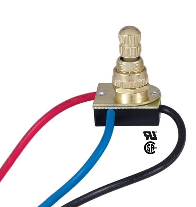
Amazon Com B P Lamp 3 Way 4 Position 2 Circuit Rotary Switch With Removable Knob Industrial Scientific

Blue Sea Systems Ac Rotary Transfer Switches

Rotary Switches Details About Umschalter Lw26 2 3 Position 4 12 Terminals 220 380v Nockenschalter Drehschalter Business Industrial Switches
Euro Pound Sterling Us Dollar Agincoat Store 0 0 00 Your Shopping Cart Is Empty Navigation Non Fused Switch Disconnectors Push Button Switches Rocker Switches Rotary Switches Toggle Switches 4 Positions Rotary Switch 20 A Rotary Knob Home 4
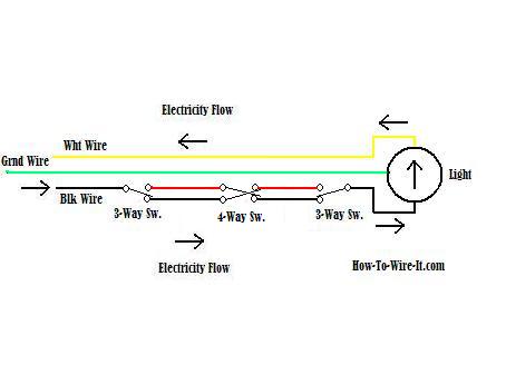
Wiring A 4 Way Switch

Buy Taiss Universal Changeover Switch 20a 550v 4 Position 8 Terminals Latching Rotary Cam Selector Switch Sv2 4s Blue Connection Terminal Lw26 20 0 4 2 Online In Indonesia B08gr2344m
Rotary Switch 1 Pole 8 Positions 1 80

Rotary Switch Wiring The Gear Page

4 Position Rotary Switch Off Low Medium High For Fan Heater New 3 99 Picclick

Rotary Switch Wiring Diagram Kabel Listrik Kabel Sakelar Listrik Pignout Sudut Teks Png Pngegg
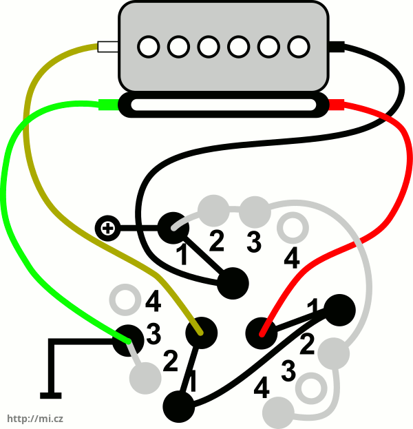
Wiring Diagram For P Rail Pickups With Rotary Switch Seymour Duncan Shpr 1 Micz Flor

Srbm Series Basic Information
Rotary Switches 4position 3speed Fan Selector Rotary Switch Governor With Knob 13amp 120v 250 Mo Business Office Industrial
0 Response to "41 4 position rotary switch wiring diagram"
Post a Comment