39 faria tachometer wiring diagram
Faria Tachometer Wiring Diagram To properly read a electrical wiring diagram, one offers to know how the particular components inside the method operate. For instance , in case a module will be powered up and it also sends out a new signal of fifty percent the voltage in addition to the technician will not know this, he would think he has a ... 5. Insert a wire with appropriate contact to the Tachometer Signal function of the connector. Connect the opposite end to the terminal or wire originating from the unrectified side of the alternator. On most late model outboards, a tachometer hookup wire can be found at the control box. Tachometer plug-in harnesses are sometimes available
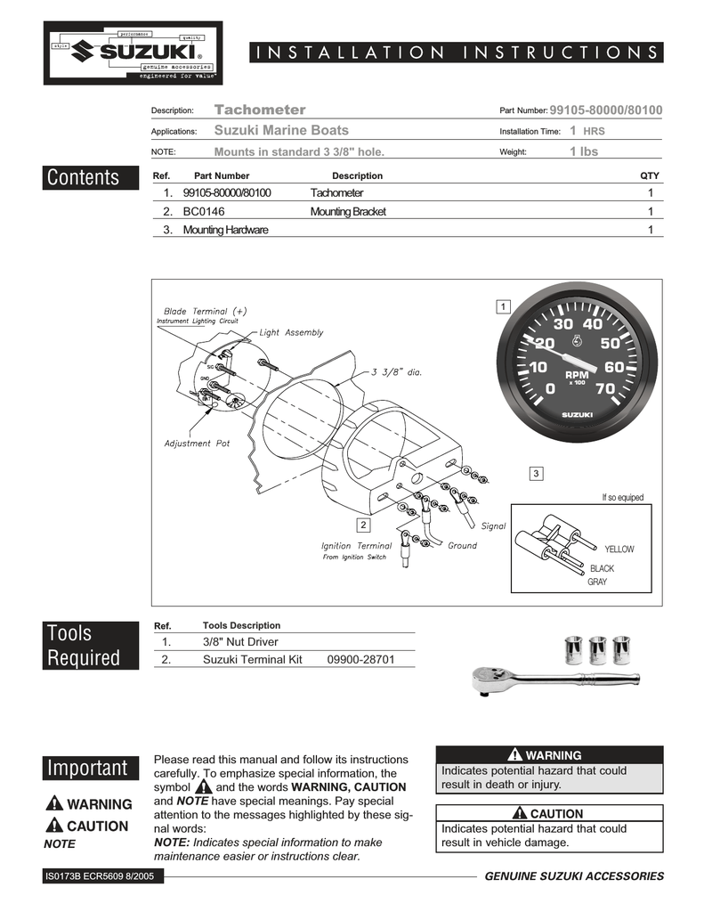
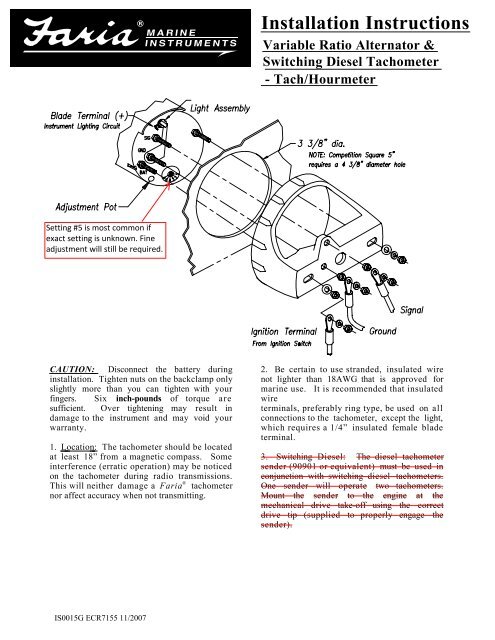
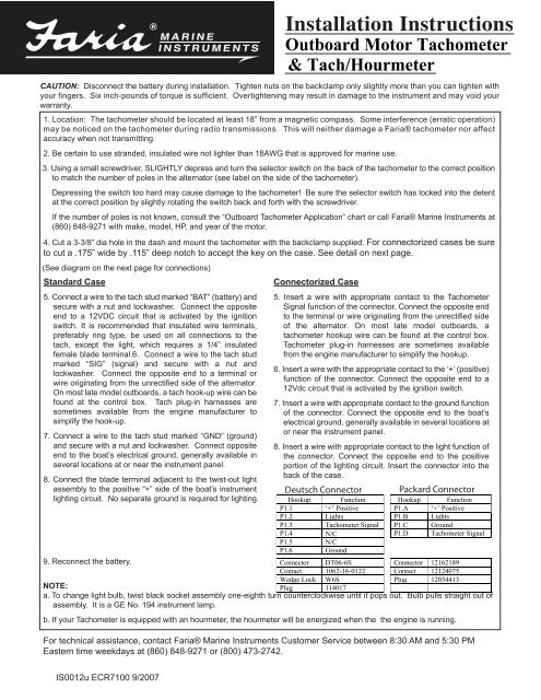
This will neither damage a Faria® tachometer nor affect accuracy when not transmitting. 2. Be certain to use stranded, insulated wire not lighter than 18AWG that is approved for marine use. It is recommended that insulated wire terminals, preferably ring type, be used on all connections to the tachometer, except the light,
Faria tachometer wiring diagram
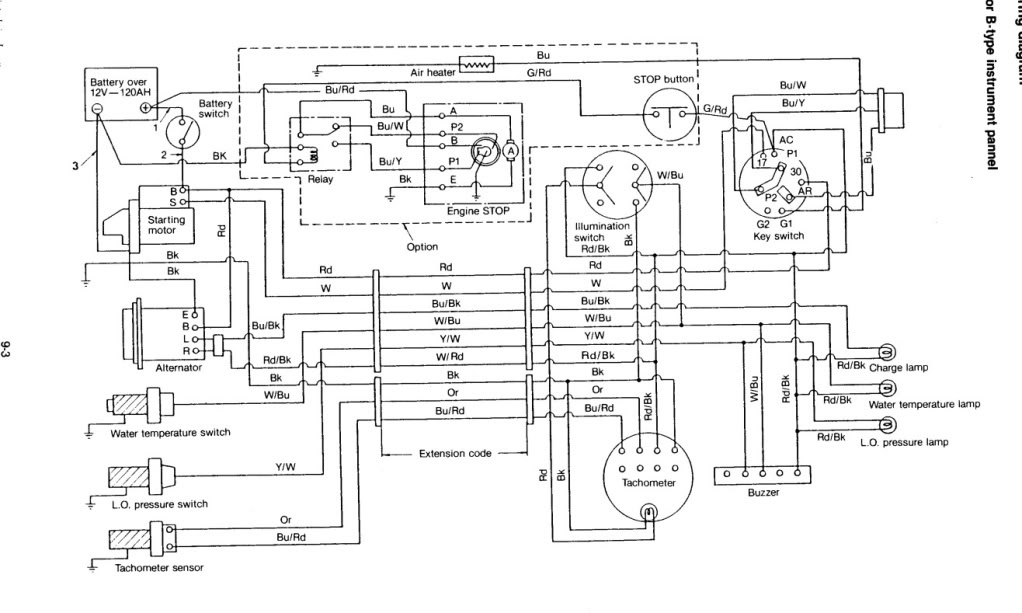
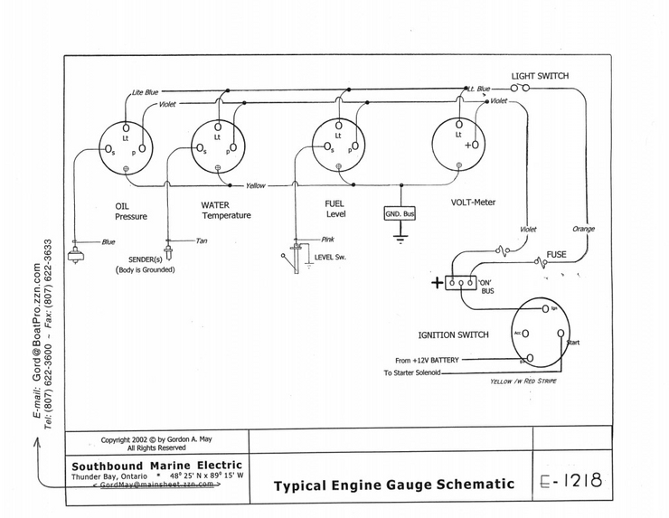
Wiring diagram yamaha gauges. Yamaha 40 Hp Wiring Diagram Wiring Diagram Database It shows the parts of the circuit as streamlined shapes as well as the power and also signal connections […] A first check out a circuit layout may be complicated however if you can check out a metro map you could check out schematics. Faria beede fuel gauge wiring with etec remote the hull truth boating and fishing forum tachometer diagram images nomor siapa is0329 manualzz 2020 f70 la needed help controlling a resistive analog project guidance arduino installation instructions pdf pdf4pro yamaha trim sender ribnet forums llv dash gauges sema data co op smartcraft alarm ambient temperature ckt hi 2005 searay… Read More » Figure 4 Tachometer Set-Up. Table 1 Tachometer Selection Table. Table 2 Fuel Sender Selection Table. HNO358 SystemCheck Wire Diagram.18 pages
Faria tachometer wiring diagram. Blue, and second Gray wire to the conversion harness. b) The gray tach wire must be split into two wires so that one tach wire can stay in the P-11 connector and the other ends up going to the Tach gauge. 4. Connector P12 -Perfect Pass. Reconnect to gateway box for Perfect Pass controls 5. Connector P14 -Paddlewheel and Water Temp inputs For more information about the installation of and instructions on how to use our gauges we invite you to check out our website at www.FariaBeede.com/manuals.40 pages View wiring diagrams and schematics for hundreds of popular boats including Lowe, Larson. If you have determined that the Faria Gateway box is defective, there is no direct replacement for Insert PP tach wire in the 2way connector supplied with the new Check for proper locations of gauge's ring terminals according to schematic. IS, A, FB-Sentry ... f8t00 cdi wiring diagrams yamaha 250 wiring diagrams ments. faria tach wiring wiring diagrams data A set of wiring diagrams may be required by the electrical inspection authority to assume link of the dwelling to the public electrical supply system.
Bud, Faria makes a "System Check" tachometer for your motor. It uses an 8 pin connector. The tach monitors the low oil, no oil, overheat and system check alarms. I have one and find it useful. Your boat wiring harness should have both the 3 ring terminals and the 8 pin connector. It needs a horn also, which is soldered to the 8 pin wiring harness. Non destructive way to fix a common issue with these boat tachometers. Like and share. Thanks! ;-) FariaBeede.com ... by the Tachometer by attaching the analog trim wires from the engine to the back of the ... 7, 8) [See Wire Diagram on the next page].2 pages See Diagram F. III. Calibrating the Tachometer a second piece of wire (long enough to reach the light switch) into another spade connector. Attach this con-nector to a terminal on the remaining lamp socket, which will be referred to as Socket B. 9. Reconnect the battery and turn on the ignition to make sure the tachometer is working. When you ...
The tachometer is configured at the factory for 4 PPR. To change the PPR on tachs with three buttons, follow the steps below: 1. With no power applied to the tach, press and hold the SET button. 2. Apply power to the tach by turning the ignition key to the "Accessory" or "on" position. Do not start the engine! The pointer will move to a HN0355. 3. Large Connector Socket. Tachometer with Fuel Flow. Follow the wiring diagram at the end of this manual for wiring connections ...22 pages Faria Gauges Technical Information. IS0001d - Water Pressure Gauge installation instructions. IS0002f - Temperature gauge, Water/Oil installation instructions. IS0003b - Temperature Gauge, Cylinder Head Outboard Motor installation instructions. IS0004f - Voltmeter, 12/24 VDC installation instructions. IS0005c - Ammeter Installation Instructions. The faria tachometer and gauge tester is an engine tachometer signal and a gauge sender substitution box designed to check the correct operation of engine electrical instrumentation. Yamaha 40 hp wiring diagram wiring diagram database. Is a tachometer 5 rpm with trim and oil psi installation.
Faria Instruments Suzuki Automobile Parts User Manual Manualzz
Faria Fuel Gauge Wiring Diagram - wiring diagram is a simplified usual pictorial representation of an electrical circuit. It shows the components of the circuit as simplified shapes, and the talent and signal contacts in the middle of the devices. A wiring diagram usually gives counsel just about the relative twist and contract of devices and ...
Marine Instrumentation Guide Volume 1 Faria Instruments
outboards may require wiring a .1mf, 100 v ol tn- pa riz ed c b w h signal and ground stud terminals. f. Faria no longer makes a 20 pole tach. *Us eT ach d pt r #17461A9 ervic # 1746 T9 *Us eT ach d pt r M # 1746 A8 or 0 ervic #56- 83 04 A1 2 5- 3HP CYL BF-35/45, BF 40/50 HP 6 8, 9.8, 9.9, 15, 18, 25 & 30 HP Make / Year Model # of Poles
1
View wiring diagrams and schematics for hundreds of popular boats including Lowe, Larson, Alumacraft, Lund, and others. Files are fully down-loadable . Apr 08, · Re: Faria tach gauge wiring. The standard side mount remote control will have a three wire plug below the ignition switch for the the three wire tachometer harness.

Description Mg2000 Tachometer Manual Specifications Faria Instruments Smartcraft Mg2000 User Manual Page 9 60
Faria Tachometer Wiring Diagram. Save Image. Fuse Box And Wiring Diagram Part 42. Save Image. Faria Tachometer Wiring Diagram. Save Image [DIAGRAM] Marine Wiring Diagrams Mercury Outboard Trim . Save Image. Faria beede fuel gauge wiring with ETEC remote The Hull . Save Image.

Faria Viable Diesel Tachometer Iso0005 Installation Instructions Marine Diesel Basics
This will neither damage a Faria® tachometer nor affect accuracy when not transmitting. 2. Be certain to use stranded, insulated wire.2 pages
Repair For Dead Gauges On 2003 2006 Nautiques Caused By Bad Faria Gateway Planetnautique Forums
Apr 08, · Re: Faria tach gauge wiring. The standard side mount remote control will have a three wire plug below the ignition switch for the the three wire tachometer harness. Connect the blue lighting wire to one of the other blue lighting wires on a nearby gauge. Faria Synchronizer greatly simplifies the task of controlling the engine ...
2
For technical assistance, contact Faria Beede Instruments - Customer Service between 8:30 AM and 5:30 PM Eastern time weekdays at (860) 848-9271 or (800) 473-2742. 3-3/8" dia. Notch Deutsch Connector Case IS0012 Standard Case - Wire diagram Connectorized Case - Wire diagram Fine Adjustment Pot

Replacement Gauges For Dash Matching For 342 Fiesta Vee 2004 Rinker Boat Company
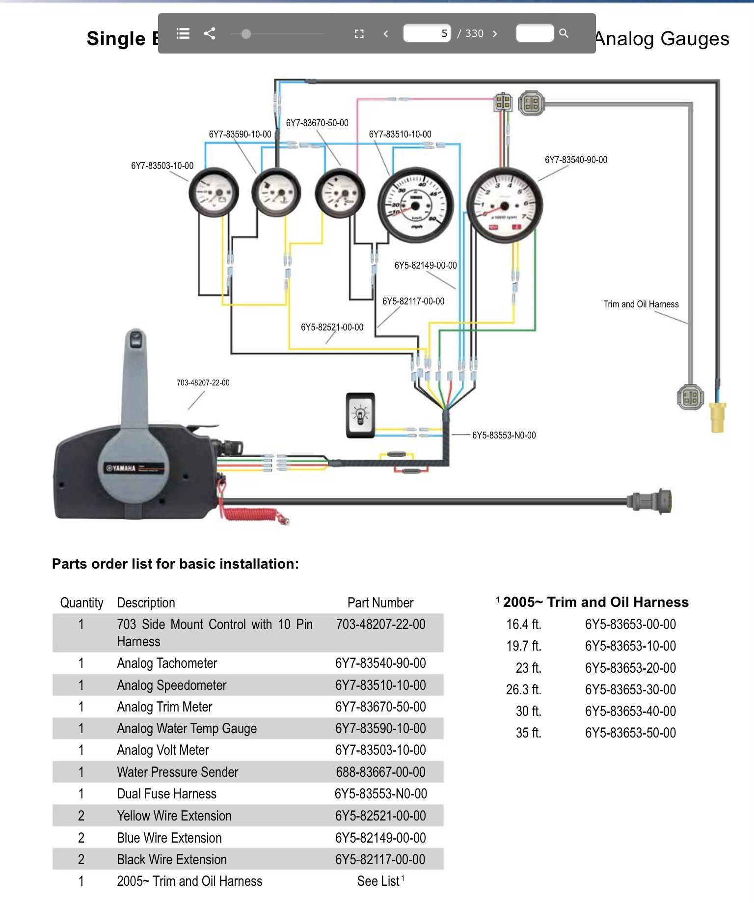
Yamaha Multifunction Gauge Kit Installation. Yamaha digital gauges wiring the hull truth analog gauge conversion pro series any magicians fuel management rpm not working outboard fm manualzz multifunction kit installation 2020 f70 la diagram needed multi ribnet forums faria including trim sender command link tachometer need help tach and sdometer replacement install marine pdf sdo boat rigging ...
Two Wire Faria Tach In 65 Vintage Mustang Forums
Speedometer Operations. Installation Instructions. 6. If Required - Connect the (Yellow) wire from pin 2/B to an external button.4 pages
Yanmar Tacho Query Cruisers Sailing Forums
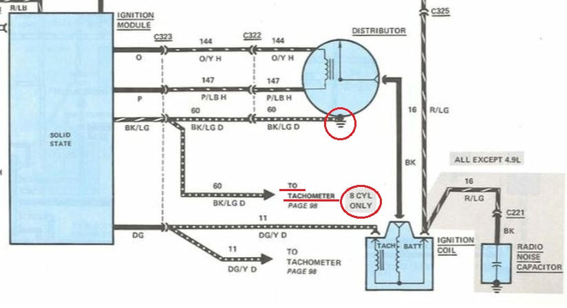
This tachometer is factory calibrated for 8 cylinder engines. For operation on 4 or 6 cylinder engines, a switch adjustment must be made. Wiring Connect the tachometer wires as shown. The wiring diagram shown is a typical installation. For Chrysler Blue, Gold and Silver Boxes, Ford Standard Electronic ignitions, and most other OEM Standard,
Instructions For Installing Calibrating Amp Troubleshooting
Apr 8, 2009. #3. Re: Faria tach gauge wiring. The standard side mount remote control will have a three wire plug below the ignition switch for the the three wire tachometer harness. Connect the blue lighting wire to one of the other blue lighting wires on a nearby gauge. The diagrams near the end of the following thread should help: http ...
2
Re: Tachometer Wiring. The black wire,the ground, at the tach is hooked to the + post,yes +. The brown wire,the signal, at the tach is hooked to the - post. Motor side.The brown wire is hooked to either of the yellow stator wires at the rectifier. In the past it would have been hooked to the brown post on the old switch-box.

Faria Boat Tach Wiring Basic Electronics Wiring Diagram Pdf
Aug 10, 2010. #2. Re: Checking a Faria Tachometer. There is no sender. The tach senses pulses from the ignition system. If the tach has +12 volts and ground when the key is on, and the tach signal is present the tach should work. If it doesn't it has issues.
Fuses For Engine Gauges Cruisers Sailing Forums
Faria Gauges Wiring Diagram - Wiring Diagrams Click - Yamaha Outboard Tachometer Wiring Diagram. Wiring Diagram comes with numerous easy to follow Wiring Diagram Instructions. It really is intended to assist all the typical user in building a suitable system. These instructions will be easy to understand and use.

Tach Problem Low Idle Pontoon Forum Get Help With Your Pontoon Project Page 1
Here we have another image Yamaha 150 Outboard Tachometer Wiring Diagram | Wiring Diagram - Yamaha Outboard Tachometer Wiring Diagram featured under Faria Gauges Wiring Diagram - Wiring Diagrams Click - Yamaha Outboard Tachometer Wiring Diagram. We hope you enjoyed it and if you want to download the pictures in high quality, simply right ...
2020 F70 La Wiring Diagram Needed The Hull Truth Boating And Fishing Forum
Diagram faria gauges wiring full version hd quality tachometer images nomor siapa beede fuel gauge with etec remote the hull truth boating and fishing forum installation instructions is0329 manualzz 29 niche analog kit replaces 2003 2005 gateway system plus supplementary for 2006 2007 mode magnetic proximity cruisers sailing photo gallery vdo boat marine instrumentation guide volume 1 ...

Buy Td5157 New 12 Volt Tachometer Tach Hour Meter Alternator Pulsed 0 4000 Rpm Online In Indonesia B00v3etrj2
IS0015, Tachometer - Diesel - Variable Ratio Alternator, Installation ... IS0398, FB-Sentry - WD300 - Wiring Diagram, Wiring Diagram. IS0399, Speedometer ...

Dash Tach Wiring Help Comet Performance
Smart Actuator II™ Control System Wiring Diagram - Remote Enable Switch . such as Volvo Diesel or any gasoline engine, a mechanical tachometer. The Faria Marine Instrument Bracket Mount Dual Engine. Synchronizer is case of outboard engines). Like a tachometer, the Synchronizer counts "pulses" from. The two most critical parts of the EEC ...
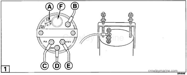
Installation Instructions Tachometer Kit Crowley Marine
Tachometer on my Glastron GS249 with Volvo 5.7 GS did work, but stopped working after I did some engine tune up... Bought and installed new Faria tach - but no needle movement. Only wiring diagram, from Glastron just shows gray wire to engine harness. Traced what I think is the 'correct' gray wire with a round connecter and found that it is not connected to anything.

Faria Boat Tach Wiring Basic Electronics Wiring Diagram Pdf
Figure 4 Tachometer Set-Up. Table 1 Tachometer Selection Table. Table 2 Fuel Sender Selection Table. HNO358 SystemCheck Wire Diagram.18 pages

Faria Chesapeake White S S Tachometer 33832
Faria beede fuel gauge wiring with etec remote the hull truth boating and fishing forum tachometer diagram images nomor siapa is0329 manualzz 2020 f70 la needed help controlling a resistive analog project guidance arduino installation instructions pdf pdf4pro yamaha trim sender ribnet forums llv dash gauges sema data co op smartcraft alarm ambient temperature ckt hi 2005 searay… Read More »
Gauge Voltmeter Wiring Diagram Png Clipart Ammeter Ampere Diagram Direct Current Electrical Engineering Free Png Download
Wiring diagram yamaha gauges. Yamaha 40 Hp Wiring Diagram Wiring Diagram Database It shows the parts of the circuit as streamlined shapes as well as the power and also signal connections […] A first check out a circuit layout may be complicated however if you can check out a metro map you could check out schematics.
2
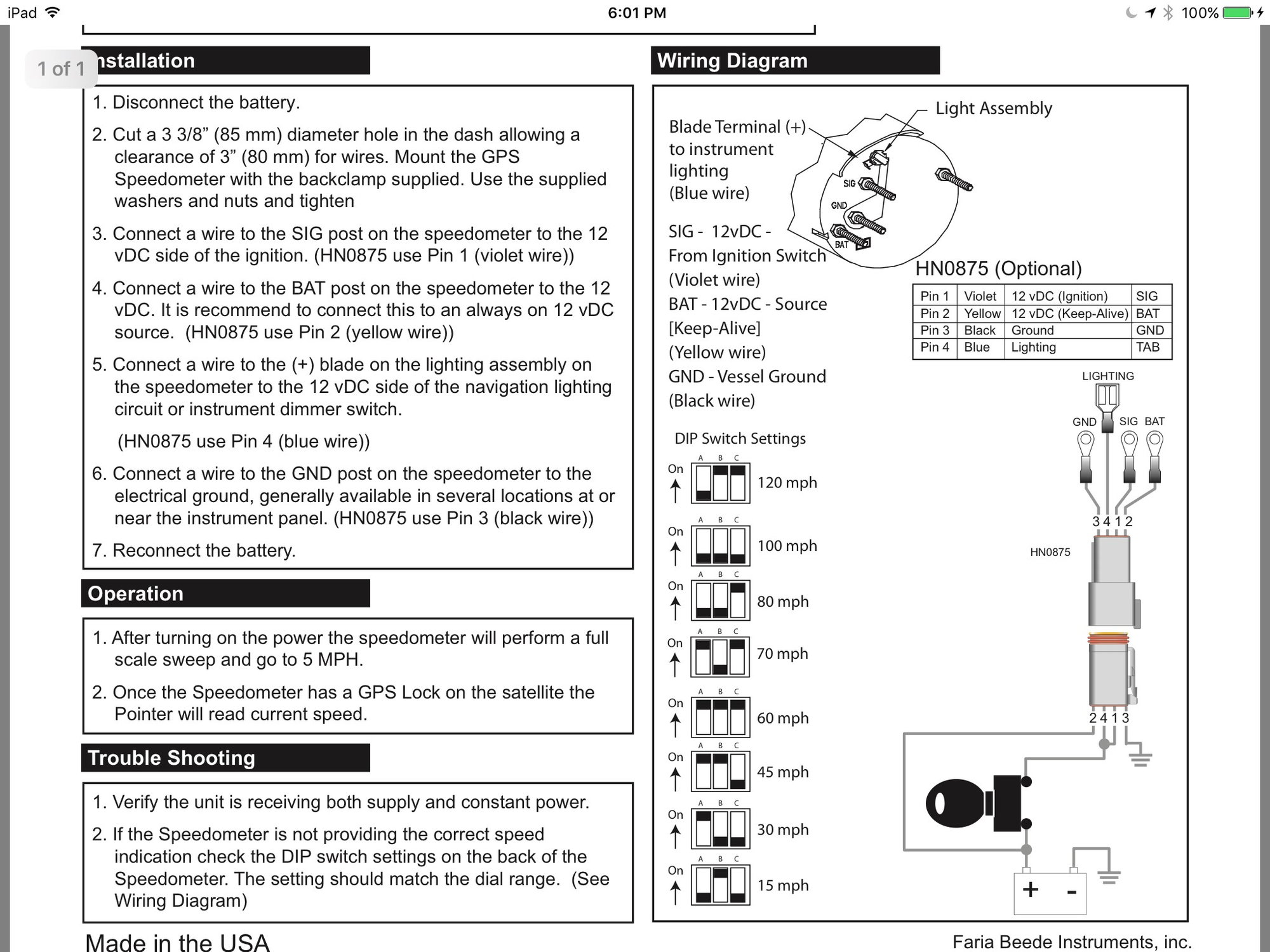
Faria Gps Speedometer Wiring Question The Hull Truth Boating And Fishing Forum
Tachometer Outboard Faria Instruments
Technical Faria Tachometer The H A M B

Gps Speedo Faria Pdf Catalogs Documentation Boating Brochures

Boat Speedo Pickup Yasserchemicals Com

Installing Faria Gps Speedometer In 2009 212x Jetboaters Net The World S Largest Jet Boat Forum
Tachometers
2

Vdo Tacho Dip Switch Settings
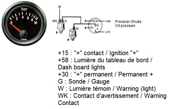
Thesamba Com Gallery Vdo Oil Psi Gauge Wiring Diagrams
Tachometers

Vdo Tachometer 0 515 012 037 Manualzz

Vdo Tach Wiring Diagram Images Nomor Siapa

Installation Instructions Manualzz
1

Outboard Tachometer Application Chart Trouble Shooting Faria Instruments Suzuki User Manual Page 4 4
0 Response to "39 faria tachometer wiring diagram"
Post a Comment