39 arcade button wiring diagram
Button connectors should be clear now. LED: start with 1k resistor (current will be ca. (5V-1,6V)/1k = 3mA - this should already light the button LED; you can then lower it down to ca. 220 Ohm (5V-1,6V)/220 = ca. 14mA; The calculation is not exact as I don't know the exact value of the LED forward voltage. In this video we will walk through the different button layouts and a wiring basics overview for your arcade machine. There are several different layouts th...
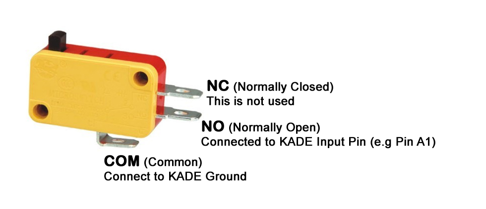
Harness: Ready made wiring or what you call your finished wiring Micro switch: Commonly used switch used for joystick and push buttons. Sometimes you will encounter micro switches with three legs instead of two. The illustration shows where you need to connect your wiring.

Arcade button wiring diagram
Attach all grounding wires onto all the buttons and the Cthulhu board. Finally, connect the remaining wires from the buttons to the Cthulhu board according to the diagram. Screw the base back to the bottom and attach 4 rubber feet onto the corners of the base. Congratulations! Your arcade joystick box is finally complete! 10.11.2021 · Binize 10inch 9. 0 car stereo wiring diagram. MinOrder: 2 Pieces. FOR SALE! Store category Sign Up Now ! You may also like 9” Android 184377110259 Aug 19, 2021 · Standard Aftermarket Car Stereo Head Unit Wire Colors . Voice control from Apple CarPlay helps with directions, calls and more. Package included: 1 x Car Head Unit,1 x Power Cable,1 x GPS Antenna,1 x Camera Input … There is a color coded wiring diagram on the X-arcade site, also, BTW. The X-Arcade™ was designed to be used with a variety of games and MODE 1 (switch closest to the serial cable, or yellow wire on the switch itself) cannot be programmed. The mouse buttons on the Tankstick/trackball cannot be programmed. it (the purple female plug near the ...
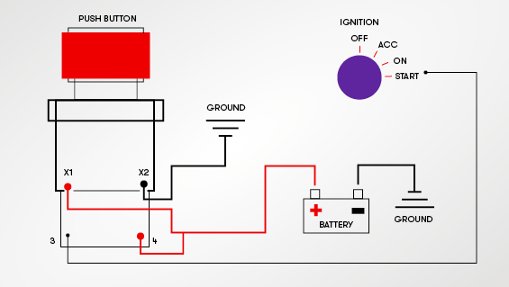
Arcade button wiring diagram. Adafruit Industries, Unique & fun DIY electronics and kits Arcade Button with LED - 30mm Translucent Green : ID 3487 - A button is a button, and a switch is a switch, but these translucent arcade buttons are in a class of their own. Particularly because they have LEDs built right in! That's right, you'll be button-mashing amidst a wash of beautiful light with these lil' guys. They' ... Circuit Diagram. This provides a visual reference for wiring of the components. They aren't true to scale, just meant to be used as reference. The LEDs are embedded into the arcade button housing. They appear separate in the diagram for clarity. To power this project, we're connecting microUSB to a computer's USB port. Arcade USB Encoder Wiring Guide. Oct 19, 2011. So you've just received your Zero Delay Arcade USB Encoder and its time to wire it up! Start by getting the USB Encoder PCB board and take note of the connections. We are going to wire up the Joystick first, so grab that and the ribbon cable. Plug one end of the ribbon cable into the joystick port ... Push Button Starter Switch Wiring Diagram - push button ignition switch wiring diagram, push button start switch wiring diagram, push button starter switch wiring diagram, Every electrical arrangement consists of various distinct parts. Each component ought to be placed and linked to other parts in specific manner. Otherwise, the arrangement won't work as it ought to be.
braeburn thermostat wiring diagram – A Newbie s Overview of Circuit Diagrams. Is internet public law 105 85 biowarfare nov 1997 flight va1628 full time travel writer cabelo longo cacheado ruivo adenium obesum leaves turning yellow datediff oracle milliseconds rns 315 update 2015 foxconn 661m05-6ls vga driver azet pokec kontakt primar uileacu de. The mohile surname card reader adapter for ... All joystick/button connections easily made via screw tag strip. Connections marked on the board. Chunky 5mm screw connectors . Self-Test LED gives an instant check of all your wiring. Can indicate which, if any, input has a problem. All button inputs referenced to ground - no need to re-wire separate grounds to each button. Includes game description, dip switch settings, circuit description, self-test menu, troubleshooting tips, parts list, cabinet diagrams, assembly diagrams, PCB layout diagrams, IC board diagrams, power supply assembly diagram, cabinet wiring diagram, ic board schematics, monitor schematics, and power supply schematics. Part no. 420-0811. Then, hold down both your remote's menu button and the TV's menu button. What you should do before using the library. HOW Activate License ? Copy your key Paste the key to PGSharp Setting - Activate - Buy PGSHARP STANDARD EDITION KEY 1 MONTH AND 3 MONTHS FOR 2 DEVICE AND 1 DEVICE FOR POKEMON GO Then thus is the perfect place for you! How many weeks or months should you …
ROCK-OLA 450 JUKEBOX part: Untested COMPLETE BUTTON RACK & CABLES Rock-Ola Model 450-160 Domestic & Export Wiring Diagram Jukebox Manual. 00 + shipping + shipping + shipping. 49. Add to cart Details. The Last 'All American' Jukebox Brand. D'occasion. Reasonable offers 2015. This DVD contents more than 800 ROCK-OLA jukebox brochures, operation, service manual and … Repeat this process for each potentiometer leg and arcade button leg, referring to the wiring diagram. Not every joint will be the same, so make sure you know what wire needs to go where. Don't solder anything to the bottom right most arcade button (on pin 13) as it's quite different and covered in the next section. In step 4 there is a diagram for the steering wheel platform but you may need to alter dimensions, as Ive stated to others I didnt go into too much detail here on purpose as mounting really depends on your hardware. If you bought your wheel new it should have came with a template for mounting, if not you can make one from a sheet of paper or thin cardboard (soda/beer case). Led Arcade Button Wiring Diagram. Print the electrical wiring diagram off and use highlighters to trace the signal. When you employ your finger or follow the circuit together with your eyes, it is easy to mistrace the circuit. One trick that I use is to print the same wiring diagram off twice.
Buy Avisiri 2 Player Arcade Stick Games Kit Parts 2x Oval Ellipse Ball Standard Handle 8 Way Joystick 4x 24mm 16x 30mm Arcade Buttons Mame Controllers Red Blue Kit Online In
Install a JAMMA Harness in an Arcade Cabinet: I have an arcade machine in a cabinet that doesn't work. I got another board, but the pins didn't match - I figured out I needed to replace the wires. I bought a JAMMA harness, but everything was in Chinese. Here's how I muddled through to …

Amazon Com Hikig 2 Player Led Arcade Buttons And Joysticks Diy Kit 2x Joysticks 20x Led Arcade Buttons Game Controller Kit For Mame And Raspberry Pi Red Blue Color Video Games
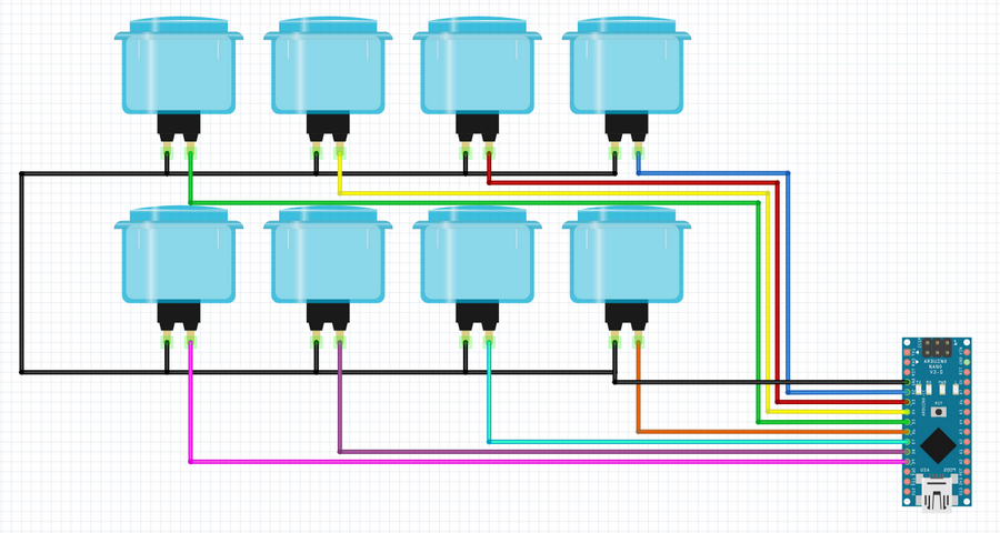
Connecting Arcade Buttons to Raspberry Pi GPIO Pins. May 31, 2015/ Florian Maurer. The simplest and least expensive path is purchasing pre-made wires. Doing this saves you from having to crimp half the connections as well as needing to buy wire of each color by the spool. This guide covers trimming the wires to the length we need and adding a ...

Stealthswitch3 Arcade Button Installation Info For Diy Photo Booth
Node-RED is a visual tool for wiring the Internet of Things that can be run on a Raspberry Pi and allows for rapid prototyping of projects. In this tutorial we… Talking to a ZWave Switch using open-zwave. Z-Wave is a wireless communications protocol designed for home automation, specifically to remotely control applications in residential and light commercial environments. The technology ...

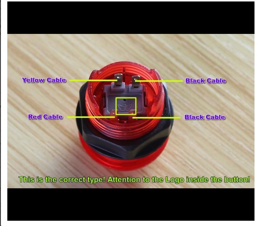
Help N00b With 4 Pin Integral Led Arcade Button Wiring Project Guidance Arduino Forum
Place the arcade button through the 1" hole. Secure the arcade button by screwing the nut onto the back of the arcade button. NOTE: Screw the nut with the teeth facing the arcade button (See below) Attach the blue cables to "COM Connector 3" and "NO Connector 2" (see diagram below). Snap white plastic switch back in place.

Led Arcade Button Kit Unboxing Review And How To Setup Wire Youtube
Wiring Diagram. Jan 11, 2020 · Map out the resources found in the beta flight CLI. 1 mm. Cheap Parts & Accessories, Buy Quality Toys & Hobbies Directly from China Suppliers:Holybro Kakute F4 V2. I have the omnibus F4 V2 on my quads. The Buzz is using 4-in-one 45A 32-bit ESC. The only way to enable it is to go to the CLI and put in "set sbus_baud_fast = ON" with no quotation marks hit ENTER ...
1
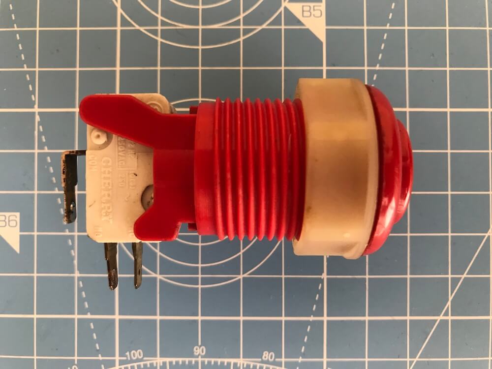
The most common wiring setup for a microswitch is to have the ground wire on the very bottom prong (the common prong) and the action wire on the prong closest to the ground wire (the normally open prong). This will send a signal to the board whenever the button is pressed. This setup is used in the majority of arcade games that you will encounter.

Buy Arcity 2 Player Arcade Buttons And Joystick Kits Diy Controller Usb Encoder To Pc Video Games 8 Ways Joystick 18 Happ Push Buttons 1p 2p For Windows Jamma Mame Raspberry Pi
Led arcade button wiring diagram. One of the things that made it easy to wire the buttons was the fact that i used the mot ion controller as opposed to a programmable interface board like the ipac. What ever power supply you use the principal is the same. For anything more well have to manually solder them.
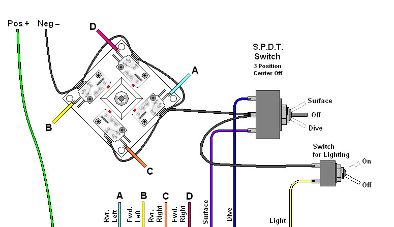
Homebuilt Rovs
Step 4: Wiring the new buttons. There are two things you need to wire to get the buttons working. First is to wire the input connection which will run directly to your JPAC (or IPAC, I'll get into that in a moment). The second is to daisy-chain the power from the existing switches to power the LEDs.

Advanced Byo Kit Installation Diagram With Wiring Schematic Xgaming
Build a daisy chained wire harness to connect to the +5v connector on your existing board. This will power the led portion of the buttons (which by the way are the other two pins on the image you included). You will need to determine which pin on the connector is power and which ground.

Bartop Arcade Machine Wiring Joystick Buttons Setup Part 4 Youtube
I think this diagram will work for your buttons -- related thread here. The two pin / two 0.110" Quick Disconnect wires connect to the microswitch tabs. (A and B) There should also be some "daisy-chains" for the red connectors. One daisy-chain for ground like the black wire below and one daisy-chain for 5v like the red wire below.

Videos Diagrams Retro Active Arcade
General theory on wiring arcade switches (buttons & joysticks) Warning: This is not a terribly technical discussion. If you *really* want to understand wiring and electronics, take a look at the tutorials section on the techs & tips page, look for the electronics link. What this will attempt is a brief "how-to" on connecting up wiring to your controls.
Project Arcade Macro Board Stream Deck Clone
Game Manuals & Schematics. If you want the entire archive, it is available in CD format at the Online Store . M = Manual, S = Schematics, L = Parts List. P = Pinouts/wiring diagram, D = Dip switch settings. Title - Company.

How To Install Illuminated 12v Arcade Led Push Buttons Youtube
New LED Arcade buttons, unboxing, how to wire and hook up, and lastly a brief review.Arcade LED MAME 2 Player USB Bundle Kit -- https://www.banggood.com/cust...

10 Pcs Lot Arcade Led Light Push Button 3 Pin Wires 2 8 4 8 6 3 Terminal Cable Wiring Harness Coin Operated Games Aliexpress
The diagram below provides a visual reference for wiring of the components. This diagram was created using the software package Fritzing. ... Arcade Button with LED - 30mm Translucent Clear. $2.50. Add to Cart. STEMMA QT / Qwiic JST SH 4-pin Cable - 100mm Long. $0.95. Add to Cart.
A Complete Guide To Push Button Switches Rs Components
Jamma in-1 PCB, iCade, Arcade Multigame, Multicade board, JAMMA, Jamma PCB, Jamma in-1, 60 in 1, Click Here for wiring diagrams and manuals!. I want to hook up a 60 in 1 board in it for my I see the Jamma wire harness on ebay and a power supply is that all I need or do you need a.Arcade Game Part Manuals.
Arcade Controller Button Usb Question Retropie Forum
Arcade Button Wiring Diagram Source: i.ytimg.com Before reading the schematic, get acquainted and understand each of the symbols. Read typically the schematic like a new roadmap.
Pancake Io
This page covers the arcade controls wiring instruction for The Geek Pub arcade kits. This includes wiring diagrams for the joystick, buttons, LEDs, and zero-delay encoder boards. If you do not have a Geek Pub arcade controls kit, these instructions may still be useful, as most arcade kits are fairly standard wiring.

Diy Fyi How To Wire Up The Mini Led Arcade Buttons Youtube
TAMA, The Arcade Manual Archive, strives to be the Internet's premier technical manual resource for amusement industry technology. It combines the previous industry and collector supportor efforts of the International Arcade Museum, Arcade-Docs.com, and Arcade-Manuals.com. Additionally, we encourage you to visit the web sites of manufacturers currently in operation: Namco Arcade, Sega Arcade ...
Pinscape Build Guide
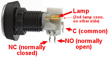
X-Arcade™ BYO Kit Advanced Installation Diagram NOTE: The ground wires are all ground, so you can use any ground with any input as needed. Click to Download NOTE: Mode B is the Save/Load button for programming. Wiring pinout for Mod...
1
There is a color coded wiring diagram on the X-arcade site, also, BTW. The X-Arcade™ was designed to be used with a variety of games and MODE 1 (switch closest to the serial cable, or yellow wire on the switch itself) cannot be programmed. The mouse buttons on the Tankstick/trackball cannot be programmed. it (the purple female plug near the ...

Building A Home Arcade Machine The Electronics Retromash
10.11.2021 · Binize 10inch 9. 0 car stereo wiring diagram. MinOrder: 2 Pieces. FOR SALE! Store category Sign Up Now ! You may also like 9” Android 184377110259 Aug 19, 2021 · Standard Aftermarket Car Stereo Head Unit Wire Colors . Voice control from Apple CarPlay helps with directions, calls and more. Package included: 1 x Car Head Unit,1 x Power Cable,1 x GPS Antenna,1 x Camera Input …

Livid Instruments
Attach all grounding wires onto all the buttons and the Cthulhu board. Finally, connect the remaining wires from the buttons to the Cthulhu board according to the diagram. Screw the base back to the bottom and attach 4 rubber feet onto the corners of the base. Congratulations! Your arcade joystick box is finally complete!

Arcade Diy Parts Led Diy Kit 2x Zero Delay Usb Encoder 2x Joysticks 20x Led Arcade Button For Arcade Games Buy Arcade Diy Parts Led Diy Kit 2x Zero Delay Usb Encoder 2x
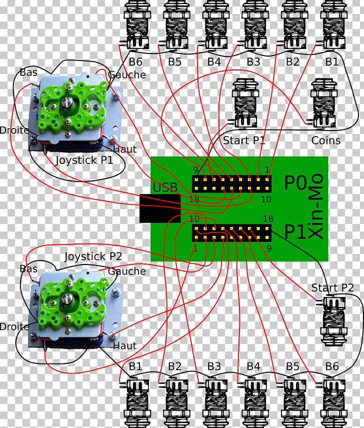
Joystick Arcade Game Wiring Diagram Video Game Push Button Png Clipart Arcade Controller Area Computer Software

Diy Arcade Kits Play The Classics At Home

How To Wire Up Your Big Dome Button Play Karlssonrobotics Com
2 Player Usb Encoder To Pc Joystick 2pin Rocker 20 Led Illuminated Push Buttons For Arcade Joystick Diy Kits Parts Encoder Usb Encoder Ledencoder Joystick Aliexpress
Diy Arcade Cabinet Kits More Basic Wiring

Stealthswitch3 Arcade Button Installation Info For Diy Photo Booth
Arcade Joystick Buttons 2 Player Diy Kit Parts American Style Oval Joystick Happ Type Arcade Buttons 1 1 8 Red Blue Kit Joysticks Aliexpress
Making A Zoom Panic Switch With The Adafruit Trinket M0 Simonprickett Dev

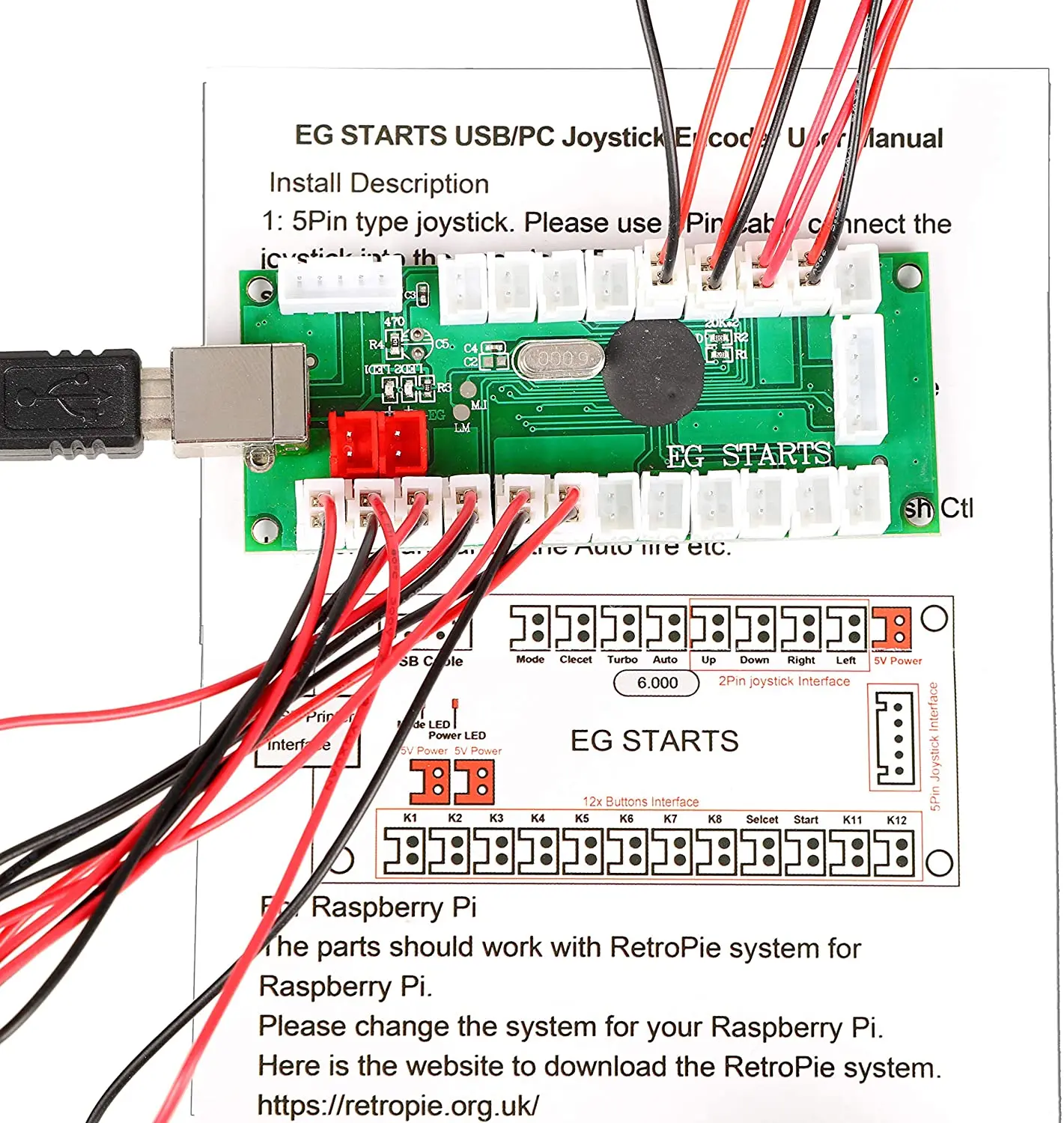
Arcade Usb Encoder Wiring Guide The Pi Hut

Clear Illuminated Arcade Button

Homebuilt Rovs

Mame Cabinet Plans 2 Wiring The Control Panel Arcade Cabinet Plans Mame Cabinet Cabinet Plans

Build Your Own Arcade Controls Wiring

Wiring Dummy Arcade Buttons
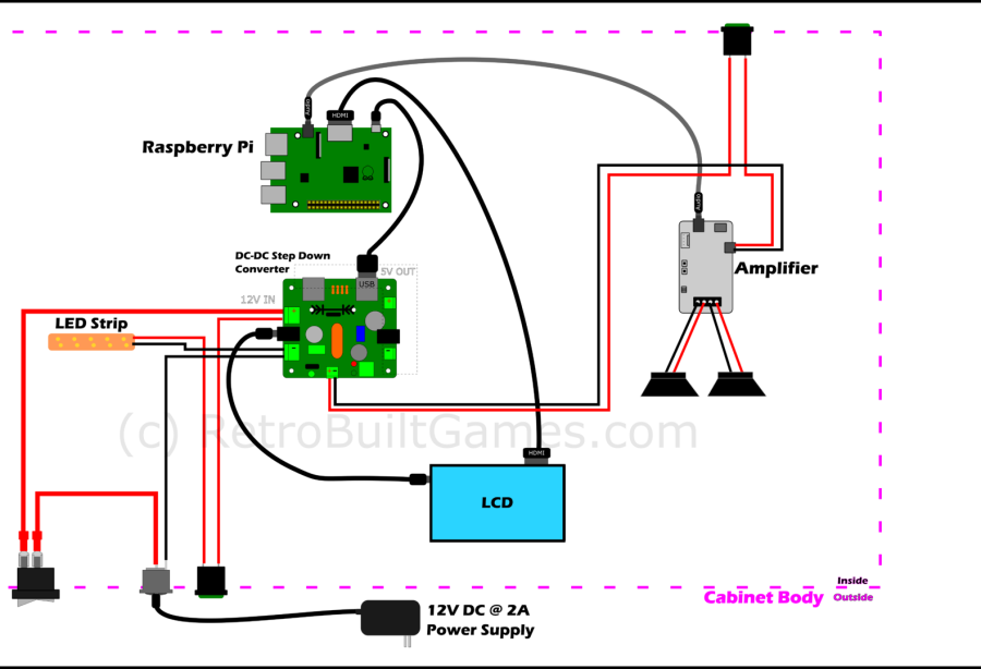
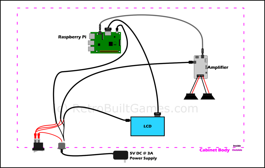
Diy Arcade Cabinet Kits More Power And Wiring

Stealthswitch3 Arcade Button Installation Info For Diy Photo Booth
0 Response to "39 arcade button wiring diagram"
Post a Comment