38 motor control circuit diagram pdf
Maxim > Design Support > Technical Documents > Tutorials > Interface Circuits > APP 4697 Keywords: motor control, industrial control, hall effect sensor, DC Motor, brushless DC, AC induction, electrical components, block diagram, TUTORIAL 4697 Overview of Industrial Motor Control Systems By: Sohail Mirza, Application Manager May 10, 2010 business. Q-circuit is a high level macro package designed to change that. With Q-circuit, drawing quantum circuit diagrams is as easy as constructing an array. In a mat-ter of minutes you can learn the basic syntax and start producing circuits of your own. This tutorial teaches you to use Q-circuit from the ground up.
Shunting Thermal Units During Starting Period. 10. Overcurrent Protection for 3-Wire Control Circuits. 11. AC Manual Starters and Manual Motor.109 pages
Motor control circuit diagram pdf
19 Aug 2020 — Transferring From Schematic to Wiring Diagram for Connection Purposes. 69. 23. Motor-Lead Connections. 73. 24. Self Test 4.189 pages The following are the circuit symbols commonly used in motor related schematic diagrams. Note: The following symbol was developed by Telemecanique and is still ...42 pages Part 2: Circuit-breakers. Part 3: Switches, disconnectors, switch-discon-nectors and fuse combination units. Part 4: Contactors and motor starters including short circuit and overload protection devices. Part 5: Control circuit devices and switching elements. Part 6: Multiple function equipment such as that used for automatic emergency power ...
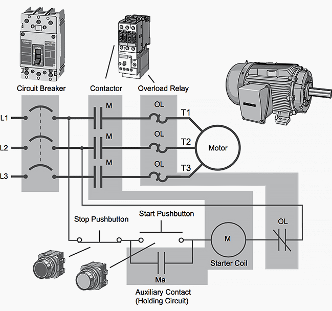
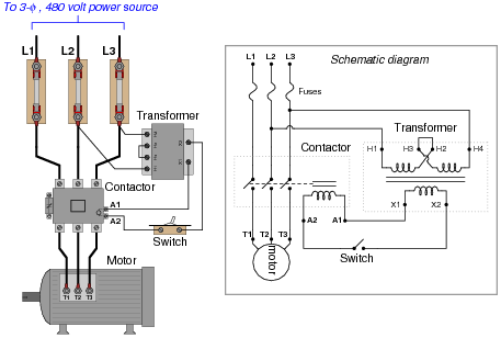
Motor control circuit diagram pdf. wiring diagram calls for something different. It is your job to improvise a solution! file 00836 Question 4 Interpret this AC motor control circuit diagram, explaining the meaning of each symbol: L1 L2 Run M1 To 3-phase motor power source M1 Also, explain the operation of this motor control circuit. What happens when someone actuates the ... 10.1 Motor Control Circuits. The interlock contacts installed in the previous section’s motor control circuit work fine, but the motor will run only as long as each push button switch is held down. If we wanted to keep the motor running even after the operator takes his or her hand off the control switch (es), we could change the circuit in a ... 3 Phase Contactor Wiring Diagram Pdf Types Of Electrical Wiring, Electrical Circuit Diagram, ... 35 Lovely Square D Manual Motor Starter Wiring Diagram. Motor Control Panel Wiring Diagram Pdf– wiring diagram is a simplified within acceptable limits pictorial representation of an electrical circuit.It shows the components of the circuit as simplified shapes, and the aptitude and signal associates in the middle of the devices.
Diagram wiring forward reverse 3 phase motor full version hd quality starter learn electrician control using plc ladder logic tutorials point dc with timer ic implementation of circuit interlocking circuits electronics textbook pdf archives inst tools auto star delta and for electrical applied electricity the direction scientific typical direct on line nick academia edu switching single ... manual control circuit of a pushbutton controlling a pilot light. ▫ A line diagram may be used to illustrate the control and protection of a 1φ motor using ...37 pages the electrical circuits shown, wired in parallel to each other, and a corresponding multi-pole permanent mag-netic rotor. For two circuits there are two electrical rev-olutions per mechanical revolution, so for a two circuit motor, each electrical commutation phase would cover 30 degrees of mechanical rotation. Sensored Commutation Wiring diagrams show the connections to the controller, ... Figure 1 is a typical wiring diagram for a three-phase magnetic motor starter. ... Format: PDF.Download: Right here | Video Courses | Memb...Title: Basic Wiring for Motor Contol – Technical ...Size: 946 KB
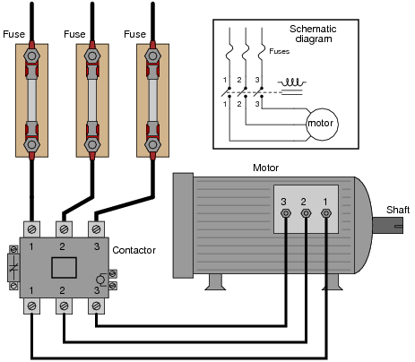
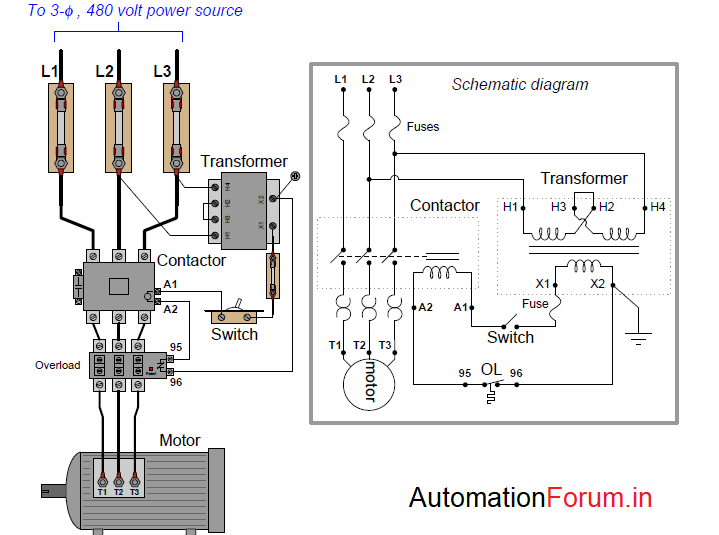
Motor Control Wiring Diagram Pdf – wiring diagram is a simplified usual pictorial representation of an electrical circuit. It shows the components of the circuit as simplified shapes, and the facility and signal associates with the devices. A wiring diagram usually gives assistance just about the relative point of view and bargain of devices ... The control circuit is separate from the motor circuit. The control circuit may not be at the same voltage as the power circuit. When the voltage of the control and power circuits is the same, it is referred to as Common Control. If the volt-ages are different, it is called Separate Control. Figure 4. Typical Starter Wiring Diagram — Three-Phase ECC0-SD Wiring Diagram. 1-800-633-0405. eMS-18. For the latest prices, please check AutomationDirect.com. Book 2 (14.3). Motor Controls ...130 pages Industrial Motor Control Circuits. Electrical motor circuits can be presented as: Block diagrams. Single line diagrams. Wiring diagrams. Schematic diagrams.12 pages
Basic Plc Program For Control Of A Three Phase Ac Motor
Part 2: Circuit-breakers. Part 3: Switches, disconnectors, switch-discon-nectors and fuse combination units. Part 4: Contactors and motor starters including short circuit and overload protection devices. Part 5: Control circuit devices and switching elements. Part 6: Multiple function equipment such as that used for automatic emergency power ...
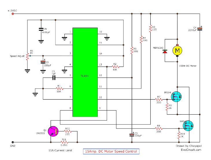
12v 24v Pwm Motor Controller Circuit Using Tl494 Irf1405
The following are the circuit symbols commonly used in motor related schematic diagrams. Note: The following symbol was developed by Telemecanique and is still ...42 pages
Ac Motor Control Circuits Worksheet Ac Electric Circuits
19 Aug 2020 — Transferring From Schematic to Wiring Diagram for Connection Purposes. 69. 23. Motor-Lead Connections. 73. 24. Self Test 4.189 pages
Mikeholt Com

3 Phase Motor Control Circuit Diagram Rig Electrician Training Youtube
Troubleshooting Three Basic Hardwired Control Circuits Used In Starting Electric Motor Eep
Ac Motor Control Circuits Worksheet Ac Electric Circuits
Basic Wiring For Motor Control Technical Data Guide Eep
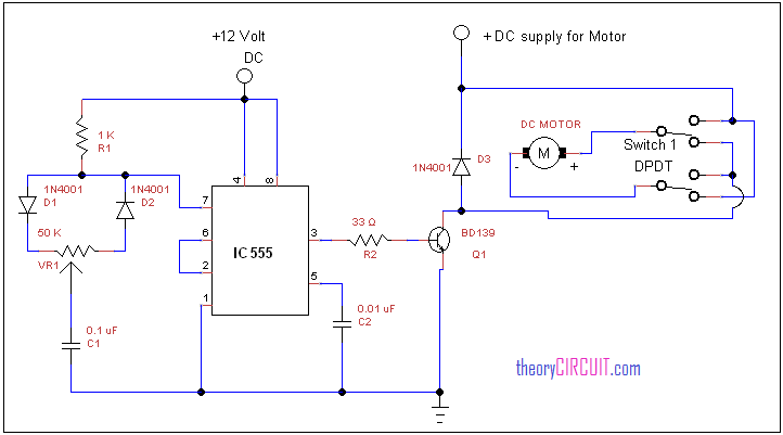
Forward Reverse Dc Motor Control Diagram With Timer Ic

Electrical Engineering World 88 Motor Control Wiring Diagrams Pdf Download Link Https Bit Ly 326tx0x Facebook

Pdf Dc Motor Speed Control System Based On Pi Controller

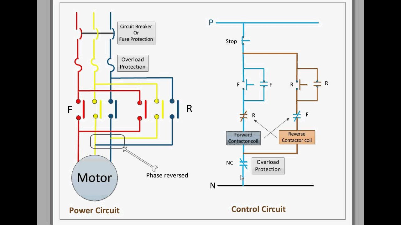
Forward Reverse Control Circuits Basic Motor Control
Motor Control Circuits Types Electrical Industrial Automation Plc Programming Scada Pid Control System
Motor Control Circuit Page 11 Automation Circuits Next Gr
Mikeholt Com
New Circuits Page 36 Next Gr

Motor Control Circuits For Android Apk Download
Motor Control Circuit Composed Of Ne555 Control Circuit Circuit Diagram Seekic Com

Motor Control Circuit Diagram Forward Reverse Pdf Archives Inst Tools
Control Circuit For Forward And Reverse Motor Youtube

Dol Starter Direct Online Starter Wiring Diagram Working Principle Electrical4u

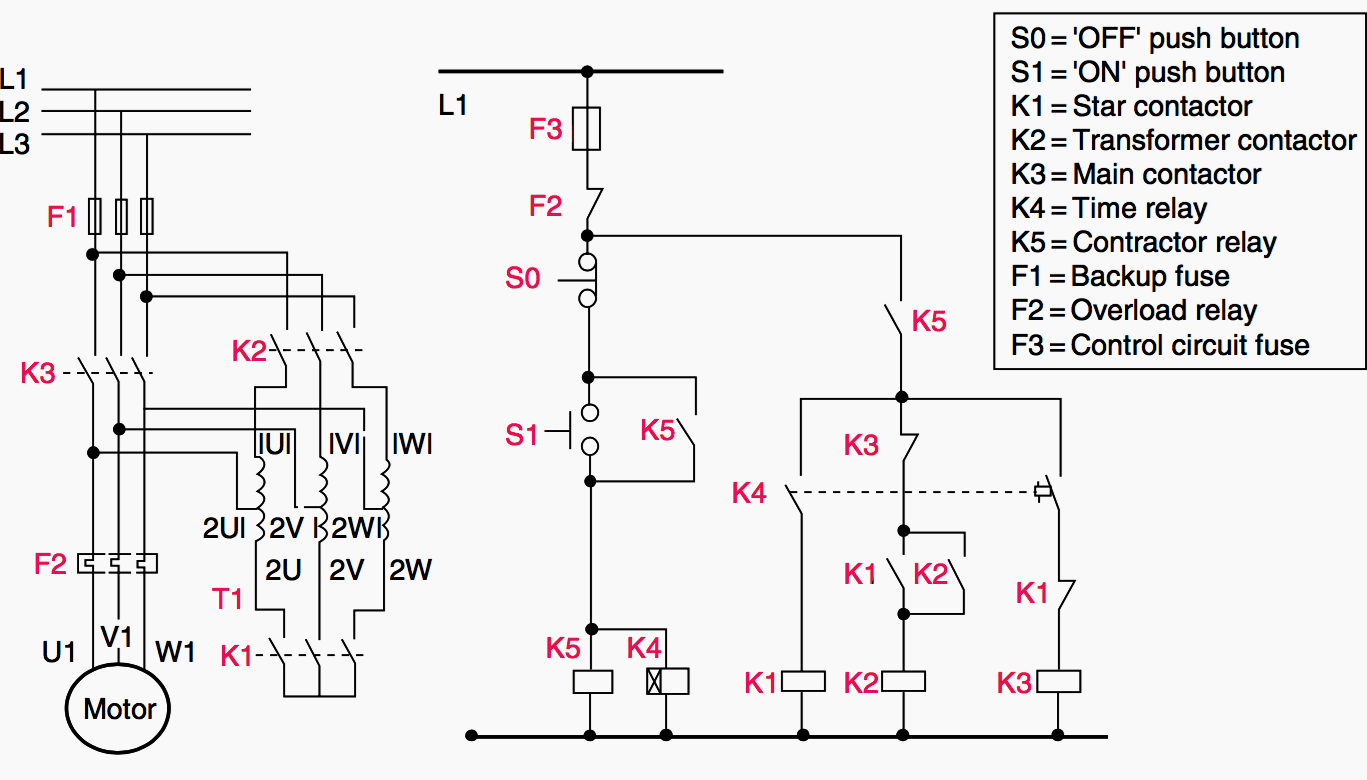
Star Delta Starter Complete Wiring For 3 Phase Motor Star Delta Control Connection Explained Youtube

2 Wire Control Circuit Diagram Motor Control Basics Controlling Three Phase Motor Youtube
Stepper Motor Circuit Page 2 Automation Circuits Next Gr

Wiring Diagram Ecu 2kd Ftv Throttle Systems Engineering Crankshaft Position Sensor Systems Engineering Ecu

Dol Starter Direct Online Starter Wiring Diagram Working Principle Electrical4u
1

Ac Motor Control Circuits Worksheet Ac Electric Circuits

Ac Motor Control Circuits Worksheet Ac Electric Circuits
1

Stepper Motor Driver Circuit Diagram Schematic Electrical4u

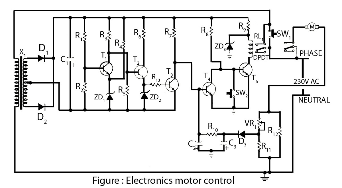
Drafting For Electronics Motors And Control Circuits Part 2

Wiring Diagram Forward Reverse 3 Phase Motor

L298n Motor Driver Module Pinout Datasheet Features Specs
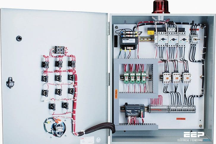
The Wiring Diagram And Physical Layout Of The Equipment Inside The Motor Control Centre Eep

Motor Control Circuit Diagram Forward Reverse Pdf Archives Inst Tools

Wiring Diagram For 220 Volt Submersible Pump Submersible Pump 1993 Ford Mustang Wiring Diag Submersible Pump Submersible Well Pump Electrical Circuit Diagram

3 Phase Star Delta Motor Wiring Diagram 3 Phase Motor Earthbondhon Youtube
0 Response to "38 motor control circuit diagram pdf"
Post a Comment