38 consider the circuit in the diagram below, in which r = 10 ω.
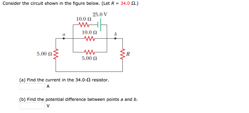
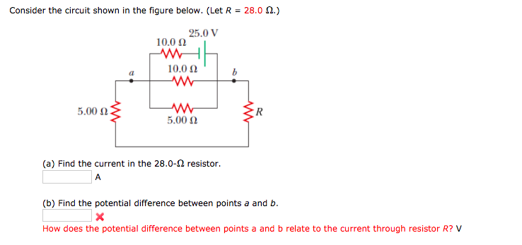
Consider the circuit shown in the figure below. (Let R = 16.0 Ω.). From point b, the circuit extends downward to a resistor with resistance R, bends to the left to reach the left end of the diagram, bends upward to reach a resistor with resistance 5.00 Ω, and returns to point a. (a) Find the current in the 16.0-Ω resistor. A (b) Find the potential difference between points a and b. Consider the circuit in diagram (a) below. What is the potential difference over the 140 kΩ resistor in this circuit? Now consider the circuit in diagram (b) below. The only difference is that a voltmeter has been added so that the potential difference could be measured. The voltmeter is the same one as the previous problem.
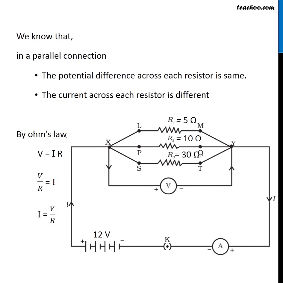
R L ω ω ω == + c R L ω= A Serial RL Circuit Result ECE 307-4 22 Frequency Response of a Circuit Example Define R and L values for a high pass filter with a cutoff frequency of 10KHz. Find |H(jω)|at 5 KHz Let We can't calculate R and L values independently. We can select R or L values then define the other RK=Ω1 c R L ω = 1000 15.9 2 ...

Consider the circuit in the diagram below, in which r = 10 ω.
Physics questions and answers. Consider the circuit shown in the diagram below. The battery has a voltage V = 12.0 V and the resistors have the following values. R1 = 2.32 2; R2 = 4.64 2, R2 = 11.60 2; R = 6.96 2 How much current flows through each of the four resistors? w RA. Question: Consider the circuit shown in the diagram below. Then an understanding of the equivalent resistance of a series circuit can be used to determine the total resistance of the circuit. Consider the following diagrams below. Diagram A represents a combination circuit with resistors R 2 and R 3 placed in parallel branches. Two 4-Ω resistors in parallel is equivalent to a resistance of 2 Ω. Example 5: RLC Circuit Consider the circuit shown below, assuming that R, L, V0 and ω are known. If both switches are closed initially, find the following: (a) the current as a function of time, (b) the average power delivered to the circuit, (c) the current as a function of time after only switch 1 is opened.
Consider the circuit in the diagram below, in which r = 10 ω.. For a parallel circuit, the R eq value is always less than the smallest of all the resistor values. Use the diagram below at the right in order to answer questions. PSYW 13. Determine the equivalent resistance of the circuit at the right. 1/R eq = (1/5 Ω) + 1/(4 Ω) + 1/(7 Ω) = 0.5928 … Ω R eq = 1/(0.5928 … Ω) = 1.69 Ω (1.6867 …Ω) 14. Draw a circuit diagram for the circuit look at picture hw 3. ... What is the direction of the current in the 30 Ω resistor in the figure? a. 0.1 A b. from left to right through the resistor. look at curcuit (hw 6) and answer questions: ... Consider the circuit shown in (hw 10). Suppose that R = 10 Ω . a. What is the equivalent resistance ... Consider the circuit shown in the diagram below. I v r eq 12 v 8 ω 1. Calculate the current through r4. The battery has a voltage v 120 v and the res. The total circuit resistance is then 10 ω ½r which is equivalent to εi 10 v05 a 20 ω 10 ω r2 in the circuit shown above the value of r for which the current i is 05 ampere is. Transcribed image text: Consider the circuit shown in the figure below. (Let R = 32.0 Ω.) 25.0 V 10.0 Ω 10.0 Ω ๕罷 5.00 Ω (a) Find the current in the 32.0-Ω resistor. (b) Find the potential difference between points a and b
Mar 21, 2014 · Homework Statement Consider the circuit shown in the diagram below, for R1 = 5 Ω, R2 = 8 Ω, R3 = 8 Ω, R4 = 8 Ω, and V0 = 8.0 V. Calculate the current through R4. Homework Equations Loop rule: The sum of all potential changes around a closed loop is zero Junction rule... Circuits ÎThe light bulbs in the circuits below are identical. Which configuration produces more light? (a) circuit I (b) circuit II (c) both the same Circuit II has ½ current of each branch of circuit I, so each bulb is ¼ as bright. The total power in circuit I is thus 4x that of circuit II. Experts are tested by Chegg as specialists in their subject area. We review their content and use your feedback to keep the quality high. Transcribed image text: Consider the circuit shown in the diagram below. The battery has a voltage V= 12.0 V and the resistor R1 3.45 Ω; R2 6.90 Ω; R3-17.25 Ω; R4-10.35 Ω How much current flows through ... The batteries in each of the circuits shown above are identical and the wires have negligible resistance. In which circuit is the current furnished by the battery the greatest. (A) A. (B) B. (C) C. (D) D. (E) E. (E) Current is greatest where resistance is least. The resistances are, in order, 1 Ω, 2 Ω, 4 Ω, 2 Ω and.
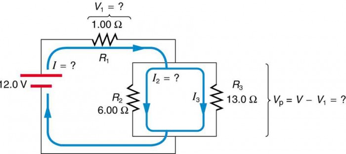
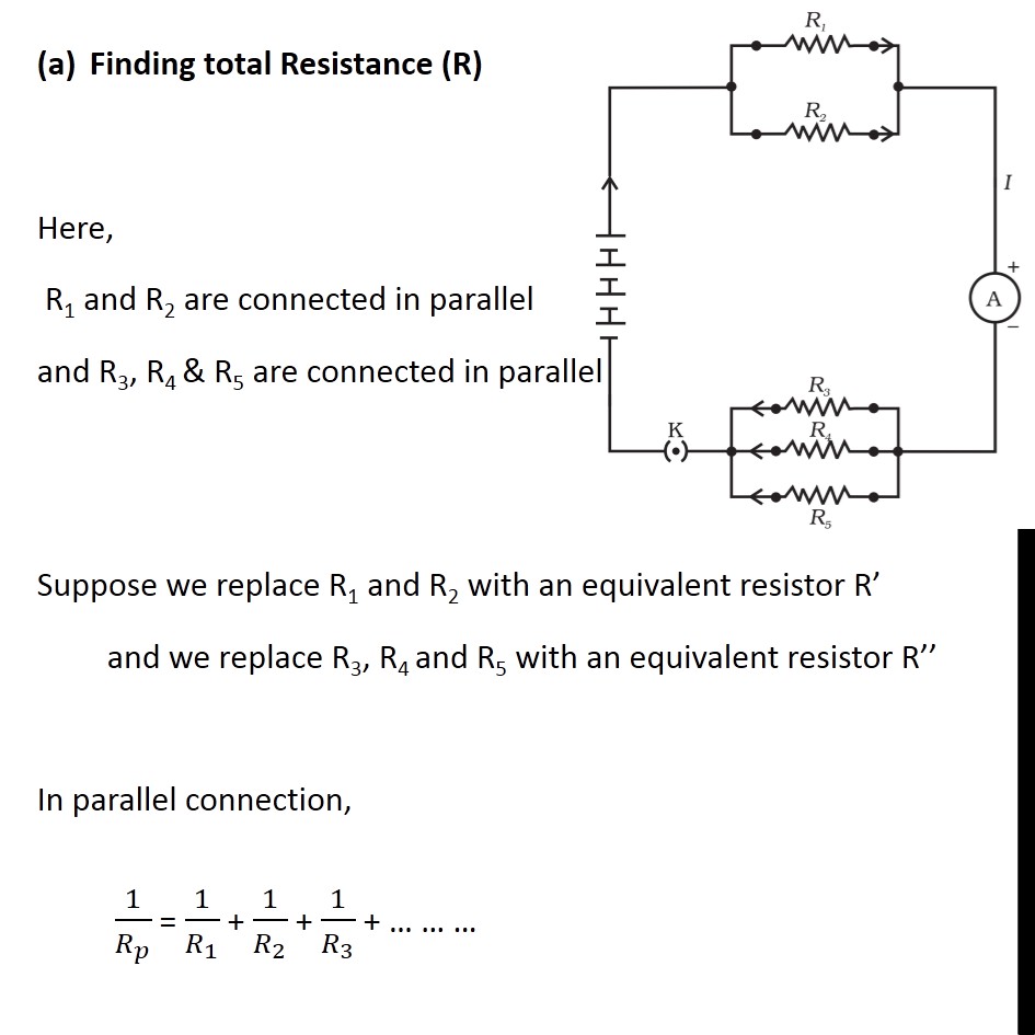
69. Four circuits have the form shown in the diagram. The capacitor is initially uncharged and the switch S is open. The values of the emf E, resistance and R, and capacitance C for each for the circuits are circuit 1: E = 18 V, R = 3 Ω, C = 1 μF circuit 2: E = 18 V, R = 6 Ω, C = 9 μF circuit 3: E = 12 V, R = 1 Ω, C = 7 μF q= (9.5 A)× (180s)=1710 C. Four 38-Ω resistors are connected in series to a 18-V battery of negligible internal resistance. Calculate the current flowing through each resistor. (You must provide an answer before moving to the next part.) The current flowing through each resistor is. Rseries= R1+ R2+ R3 +R4=4×38 Ω. current-source circuit of the figure below to provide an output current I supply V CC =5V. Give the values of IREF For Vo=5V: 3. Find the output resistance of each of the two current sources below. Let R1=942k Ω, R2=9.3k Ω, R3=11.5k Ω, V Homework #2 REF =1mA, find IO when V o=5V. Also, find the output resistance. S=10-15 A, β=100, and V A ... Example IV–1. Consider the circuit shown below, where R1 = 3.00 Ω, R2 = 10.0 Ω, R3 = 5.00 Ω, R4 = 4.00 Ω, and R5 = 3.00 Ω. (a) Find the equivalent resistance of this circuit. (b) If the total power supplied to the circuit is 4.00 W, find the emf of the battery. + − E R1 R2 R3 R4 R5 Solution (a): We have to reduce this circuit in steps. But which do we reduce
Norton Equivalent Circuit An Overview Sciencedirect Topics
Consider the circuit above. If R = 10 Ohms, L = 15 mH, and E = 15 V, what will be the value of current if t is a. 1 millisecond b. 15 millisecond c. 1 minute d. 1 hour e. 1 day
2
The radio has a. 3.20 Ω. 3.20 Ω resistance. (a) Draw a circuit diagram of the radio and its battery. Now, calculate the power delivered to the radio (b) when using a nicad cells, each having an internal resistance of. 0.0400 Ω. 0.0400 Ω, and (c) when using an alkaline cell, having an internal resistance of. 0.200 Ω.
Solved Obtain An Expression For I T As Labeled In The Circuit Diagram Of 1 Answer Transtutors
Consider the circuit shown in the figure below. (Let R = 24.0 Ω.) 25.0 V 10.0 Ω 10.0 Ω (l 5.00 Ω 5.00 Ω (a) Find the current in the 24.0-2 resistor 5.75 Compare the potential difference across the 10-Ω resistor, th (b) Find the potential difference between points a and b s it possible for the potential difference across any element
2
Consider the mass spectrometer shown schematically in the figure below. The electric field between the plates of the velocity selector is 900 V/m, and the magnetic fields in both the velocity selector and the deflection chamber have magnitudes of 0.950 T. Calculate the radius r of the path for a singly charged ion with mass m = 2.02 10−26 kg.

The Following Circuit Diagram Fig Shows That Resistors 2 W 4 W And R W Connected To A Battery Of E M F 2 V And Internal Resistance 3 W A
Jul 30, 2015 · D with the switch closed the resistance of the 15 ω and the 30 ω in parallel is 10 ω making the total circuit resistance 30 ω and e ir an ideal battery an ideal ammeter a switch and three resistors are connected as shown. R2 r3 r4 r1. Consider the circuit shown in the diagram below for r1 5 ω r2 8 ω r3 8 ω r4 8 ω and v0 80 v.
Solved Consider The Circuit Shown In The Figure Below Let Chegg Com
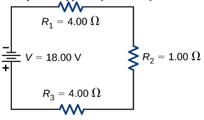
In the figure above, let R 1 = 4 Ω, R 2 = 4 Ω, and R 3 = 12 Ω. Then the equivalent resistance is R = 20 Ω. If the battery voltage is 10 V, then the current in the circuit is I = V/R = (10 V)/(20 Ω) = 0.5 A. The current through each resistor is 0.5 A. The power dissipated is P = IV = 5 W. Assume another 20 Ω resistor is added to the chain.
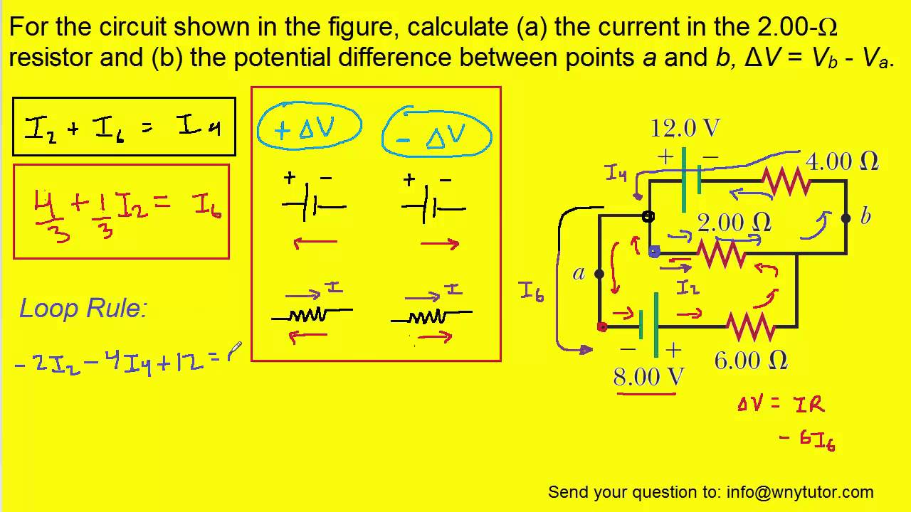
For The Circuit Shown In The Figure Calculate A The Current In The 2 00 W Resistor And B The Po Youtube
What is the value of R? a. 6. 0 Ω b. 8. 3 Ω c. 10 Ω d. 210 Ω 9. The diagram below shows a circuit with four possible meter locations. In which locations should an ammeter and voltmeter be connected to correctly measure the current through R 2 and the voltage drop across R 2? CURRENT THROUGH R 2 VOLTAGE DROP ACROSS R 2 a. 2 1 b. 2 3 c. 4 1 d ...
2
In the circuit shown below,ε = 12.0 V, r = 0.500 Ω, R 1 = 5.00 Ω, R 2 = 10.0 Ω, and C = 250 μF. Initially, the switch S is open. (a) At the instant S is closed, determine the current supplied by the battery.
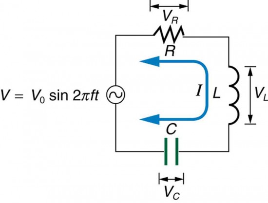
Rlc Series Ac Circuits Physics
following resistances: 100 Ω, 30 Ω, 20 Ω, and 10 Ω. The student also has plenty of wire of negligible resistance available to make connections as desired. (a) Using all of these components, draw a circuit diagram in which each resistor has nonzero current flowing through it, but in which the current from the battery is as small as possible.

In The Circuit Given Below R 13 W Using Mesh Analysis Find The Value Of B Homeworklib
Feb 29, 2020 · Consider the circuit in the diagram below, in which r = 13 ω.. Calculate the current through r4. Calculate the current through r 4. Homework equations loop rule. Randomized variables epsilon1 27 v epsilon2 48 v epsilon3 85 v epsilon4 31 v find i1 in amps. R 190 ω a find the current in the r 190 ω resistor.

Rlc Circuits An Overview Sciencedirect Topics
The total resistance of the circuit is R=Rbt+Rbulb=3.5 Ω + 19 Ω R=22.5 Ω The current through the 19-Ω resistor is I=VR=6 V22.5 Ω I=0.2667 A The voltage difference ΔVbulb across the 19-Ω resistor is calculated as follows: ΔV=5.0667 V

In The Circuit Diagram Given Below Three Resistors R 1 R 2 And R 3 Of 5 Omega 10 Omega Youtube
FREE Expert Solution. 95% (219 ratings) View Complete Written Solution. Problem Details. Consider the circuit shown in the figure below. (Let R = 36.0 Ω.) (a) Find the current in the 36.0-Ω resistor. A. (b) Find the potential difference between points a and b.

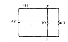
Consider The Circuit Shown In The Diagram Find The Current In 3 Ohm Resistor 302 W 1002 6 12 Cu Oz 3 Muco 4 12 V
R 1 350. Consider the circuit in the diagram below in which r 10 ω. Consider the circuit shown below. R 2 700. 016part1of3100points consider a circuit with three identical bulbs an ideal battery and a switch s. Resistance of the 30 ω and 60 ω resistors in parallel 20 ω adding the internal resistance in series with the external circuit gives ...
Consider The Circuit Shown In The Diagram Find The Current In 3 Resistor Physics Topperlearning Com Ij7jct7kk
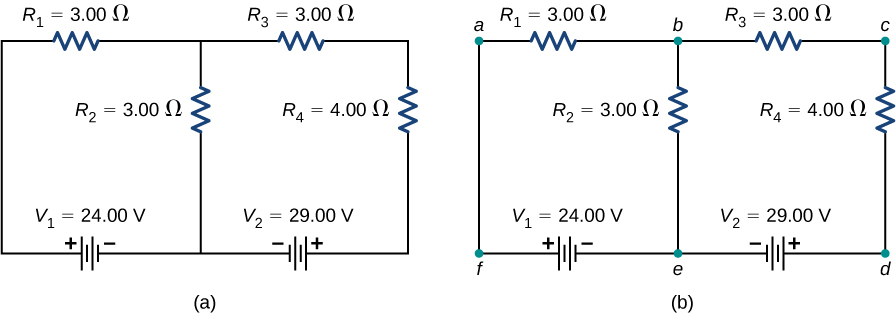
Consider the circuit in Figure 10.26(a). Let us analyze this circuit to find the current through each resistor. ... I = V 2 − V 1 R 1 + R 2 + R 3 = 24 V − 12 V 10.0 Ω + 30.0 ... The circuit diagram of the two batteries and the load resistor, with each battery modeled as an idealized emf source and an internal resistance. When voltage ...

Astable Multivibrator And Astable Oscillator Circuit
Consider the circuit shown in the diagram below. The battery has a voltage V = 12.0 V and the resistors have the following values.. R 1 = 1.82 Ω; R 2 = 3.64 Ω; R 3 = 9.10 Ω; R 4 = 5.46 Ω. How much current flows through each of the four resistors?

In The Following Circuit R1 12 W R2 18 W And R3 24 W Youtube
(A) 0.1 Ω (B) 10 Ω (C) 12 Ω (D) 120 Ω (D ) 34. When the switch S is open in the circuit shown, the reading on the ammeter A is 2.0 A. When the switch is closed, the reading on the ammeter is (A) doubled (B) increased slightly but not doubled (C) decreased slightly but not halved (D) halved 382
Solved Resistors In Series And Parallel Consider The Circui Chegg Com
P 5.4-8 A resistor, R, was connected to a circuit box as shown in Figure P 5.4-8. The voltage, v, was measured. The resistance was changed, and the voltage was measured again. The results are shown in the table. Determine the Thévenin equivalent of the circuit within the box and predict the voltage, v, when R = 8 kΩ. Figure P 5.4-8 Solution:
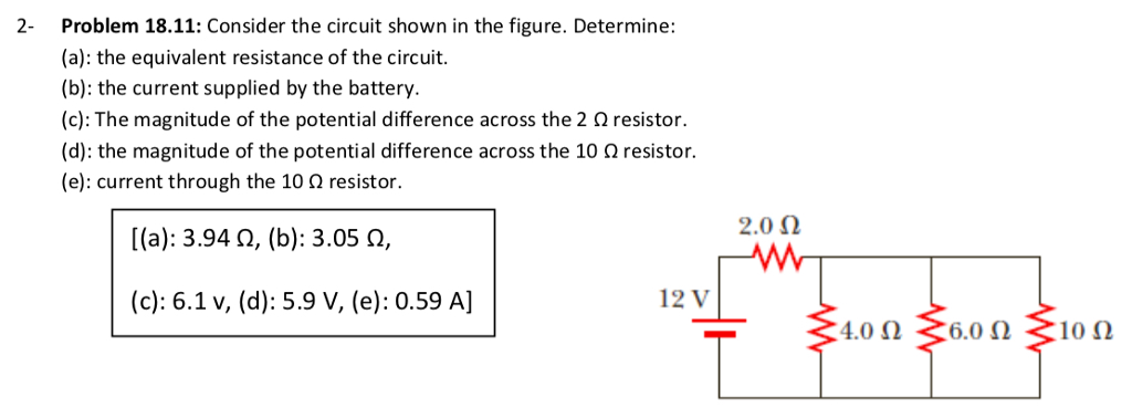
Solved Problem 18 11 Consider The Circuit Shown In The Chegg Com
The diagram below shows the circuit for a small convector heater. Heater elements can be switched in and out of the circuit using switches X and Y. Each element has a resistance R and the power supply has an emf V. (a) The table shows the possible combinations of open and closed switches. When a switch is closed, charge can flow through it. 17
Circuits Flashcards Quizlet
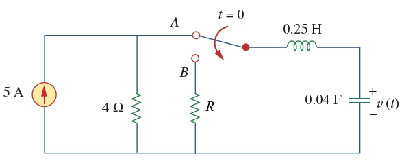
Example 5: RLC Circuit Consider the circuit shown below, assuming that R, L, V0 and ω are known. If both switches are closed initially, find the following: (a) the current as a function of time, (b) the average power delivered to the circuit, (c) the current as a function of time after only switch 1 is opened.

Current Through Resistor In Parallel Worked Example Video Khan Academy
Then an understanding of the equivalent resistance of a series circuit can be used to determine the total resistance of the circuit. Consider the following diagrams below. Diagram A represents a combination circuit with resistors R 2 and R 3 placed in parallel branches. Two 4-Ω resistors in parallel is equivalent to a resistance of 2 Ω.
Resistors In Series And Parallel Physics Ii
Physics questions and answers. Consider the circuit shown in the diagram below. The battery has a voltage V = 12.0 V and the resistors have the following values. R1 = 2.32 2; R2 = 4.64 2, R2 = 11.60 2; R = 6.96 2 How much current flows through each of the four resistors? w RA. Question: Consider the circuit shown in the diagram below.

In The Circuit Given Below R 8 W Find The Node Voltages 410 2t 12 1 A Homeworklib

11 2 Ohm S Law Electric Circuits Siyavula

Time Constant Calculations Worksheet Dc Electric Circuits
Example 12 9 If In Fig 12 12 R1 10 R2 40 R3 30 R4 20
Answered In The Circuit Given Below R 18 W Bartleby
1

1 2 9 The Diagram Below Is An Rcl Circuit With R 10 Ohms C Homeworklib
Rlc Series Ac Circuits Physics

Series Rlc Circuit And Rlc Series Circuit Analysis
2
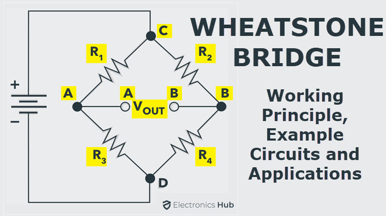
Wheatstone Bridge Circuit Theory Example And Applications
2
Kirchhoff S Rules University Physics Volume 2
Example 12 8 In The Circuit Diagram Given In Fig 12 10 Suppose The
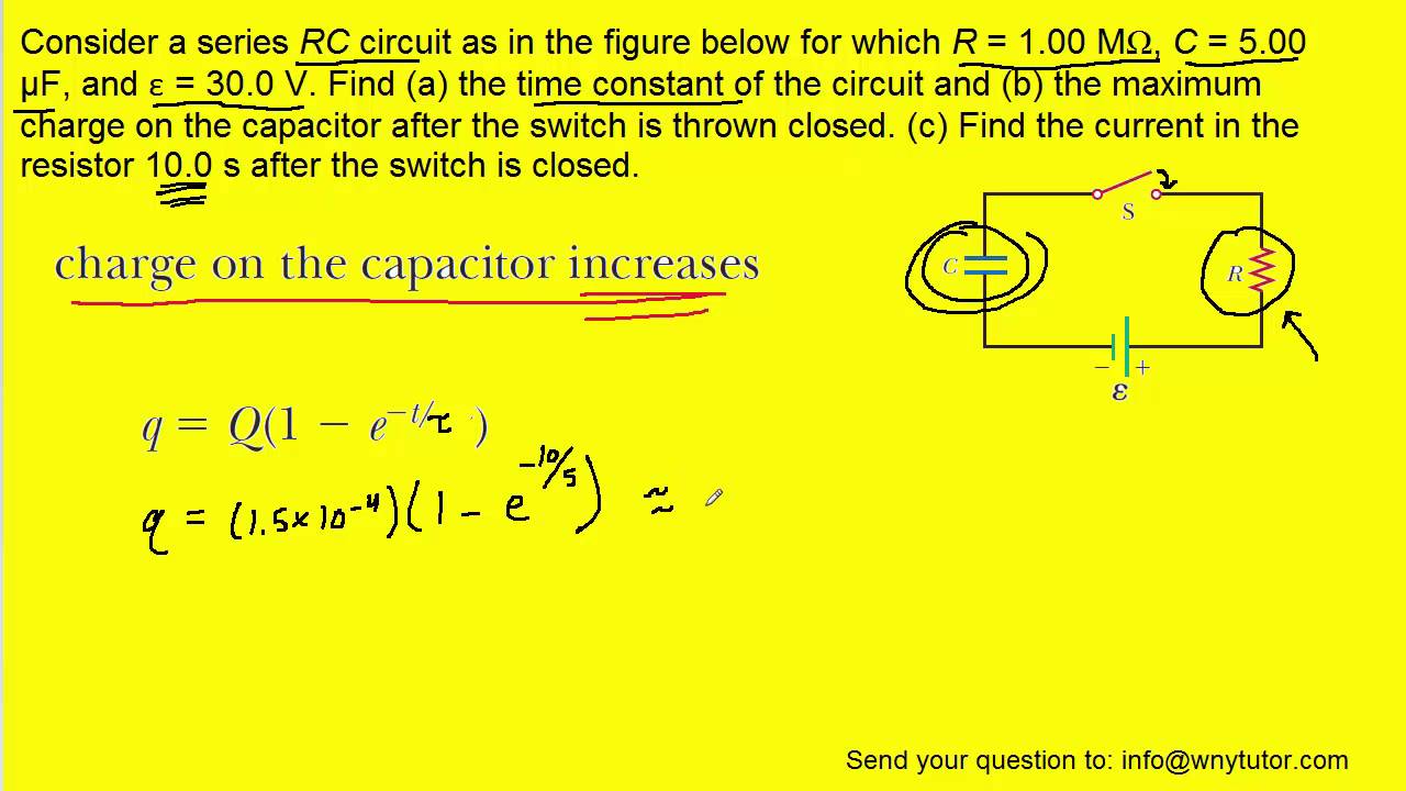
Consider A Series Rc Circuit As In The Figure Below For Which R 1 00 Mw C 5 00 µf And E 30 0 Youtube
Solved Consider The Circuit Shown In The Figure Below Let Chegg Com
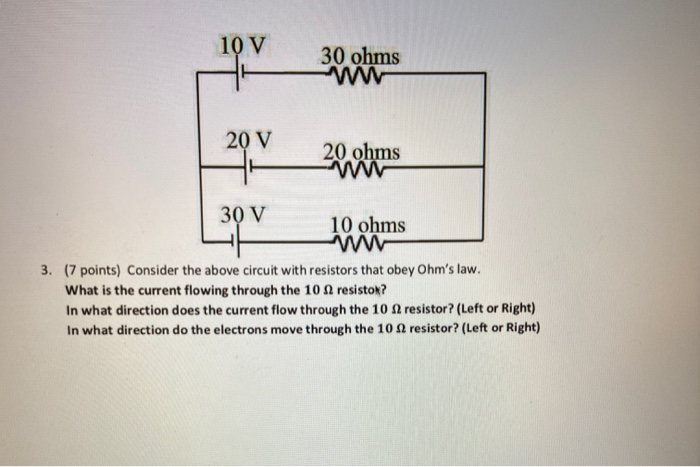
Solved 10 V 30 Ohms 20 V 20 Ohms 30 V 10 Ohms 3 7 Points Chegg Com
0 Response to "38 consider the circuit in the diagram below, in which r = 10 ω."
Post a Comment